
A Study on the Design of Isolator and the Mounting Method for Reducing the Pyro-Shock of a MEMS IMU

Abstract
:1. Introduction
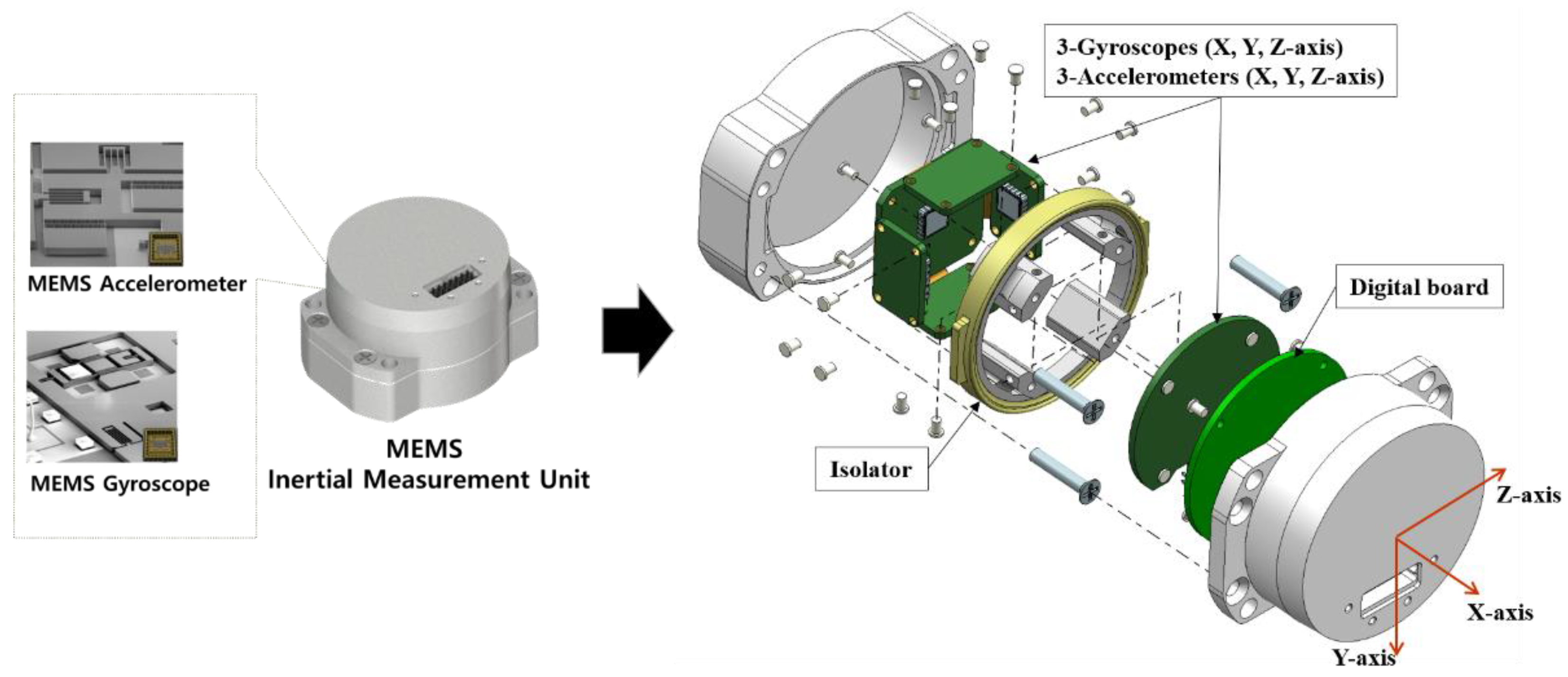
2. MEMS Inertial Measurement Unit
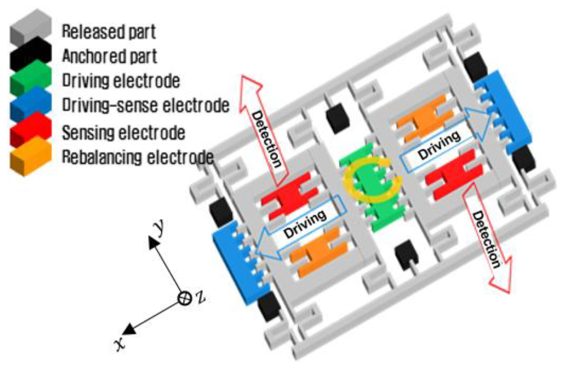
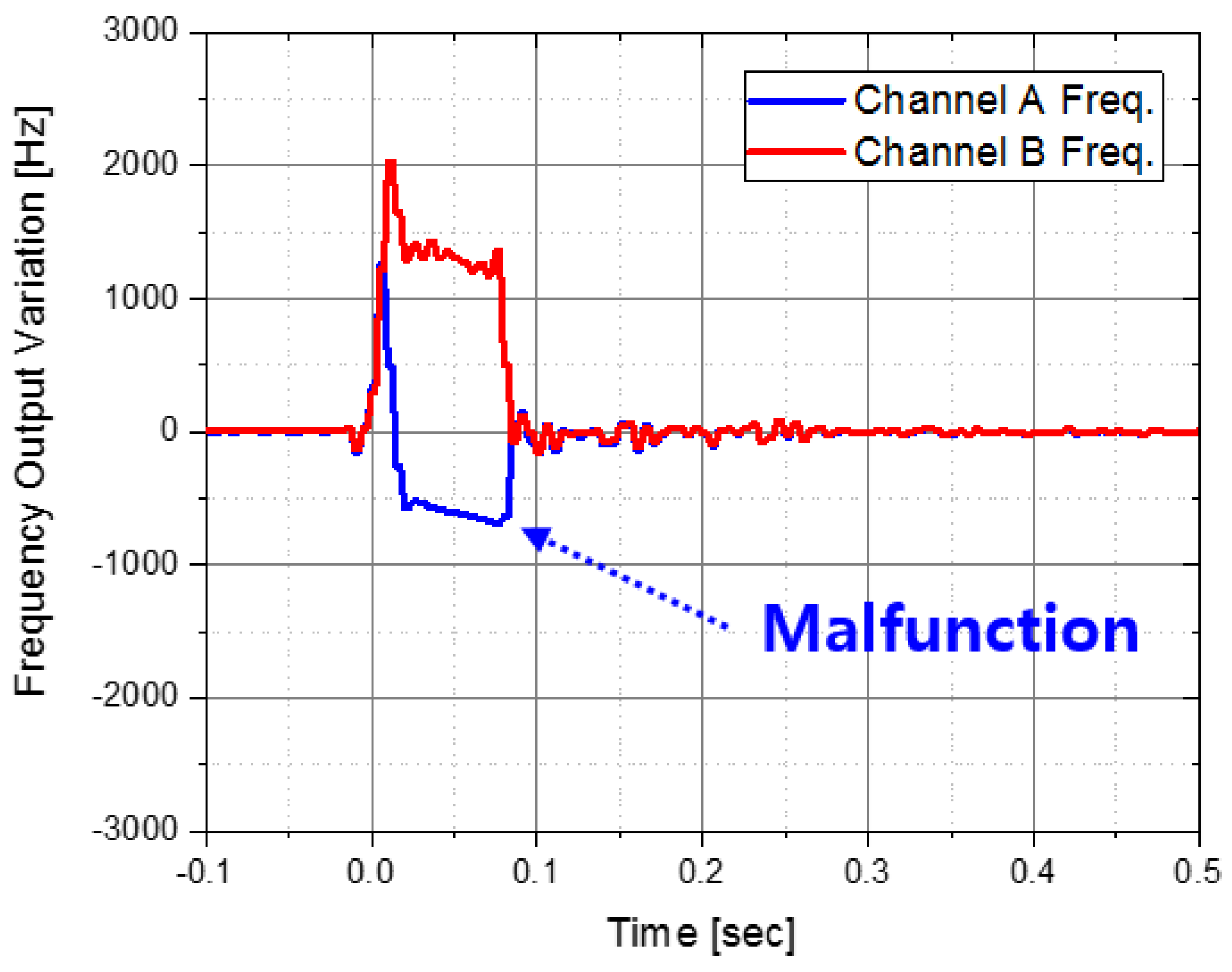
2.1. Vibratory Gyroscope
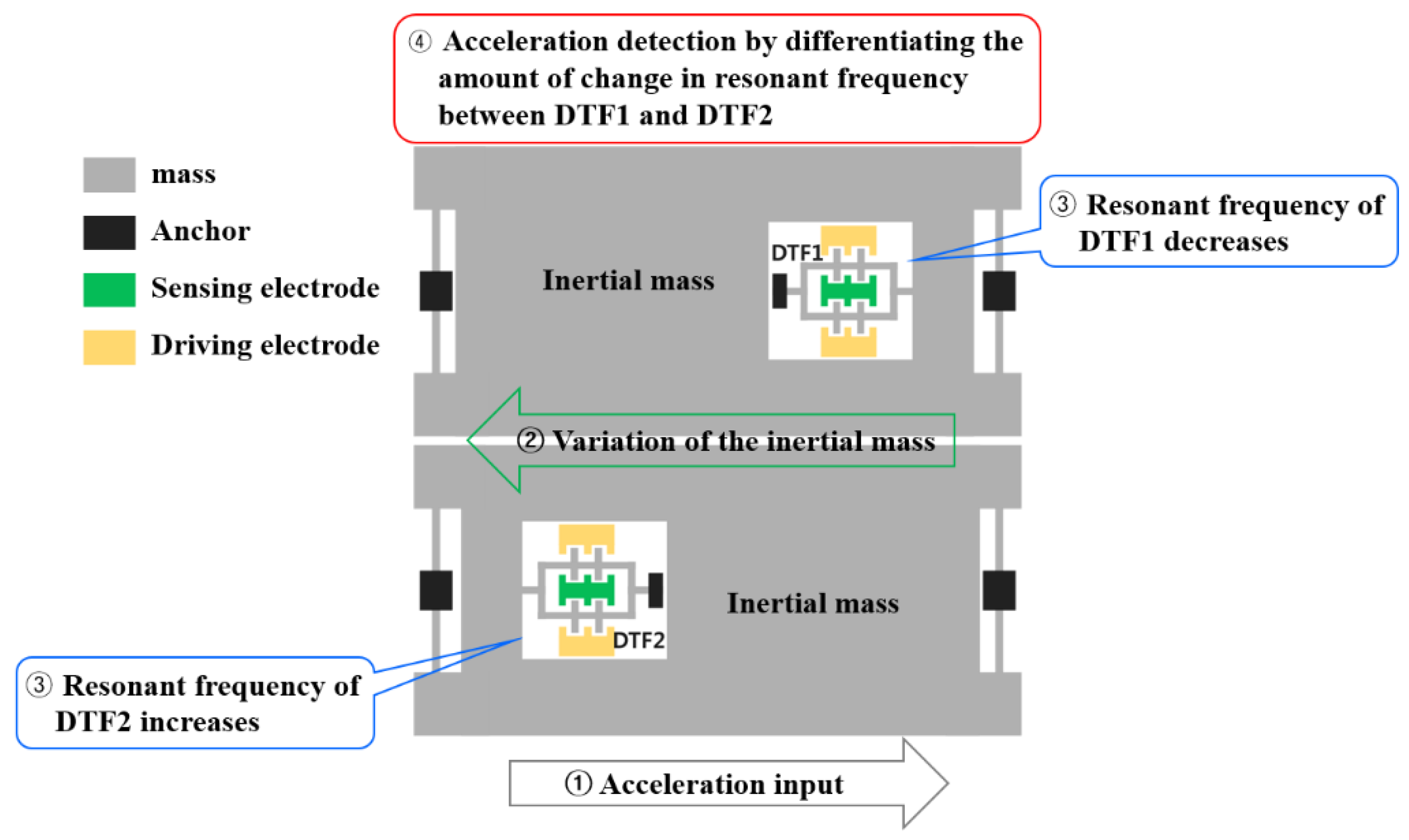
2.2. Resonant Accelerometer
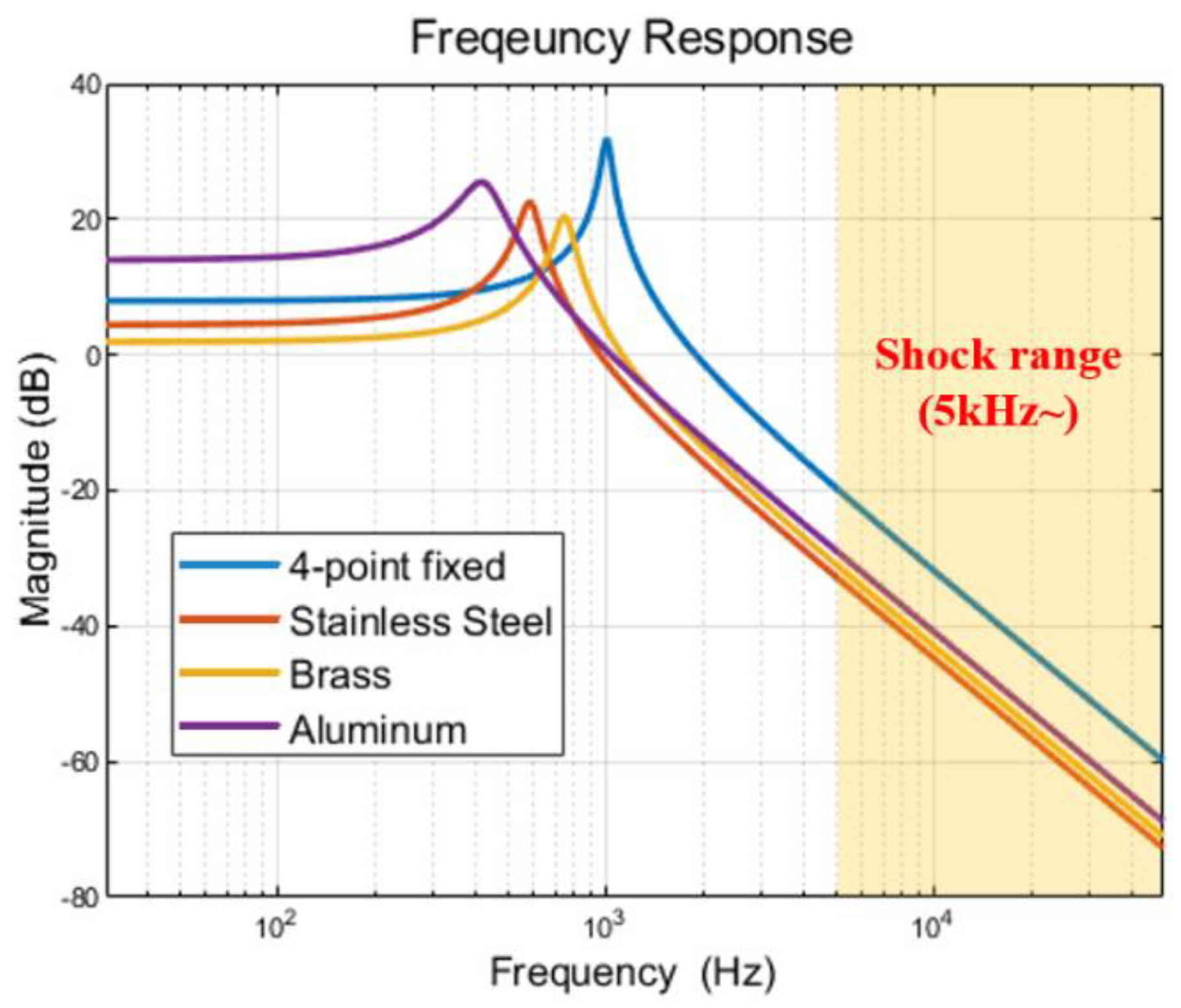
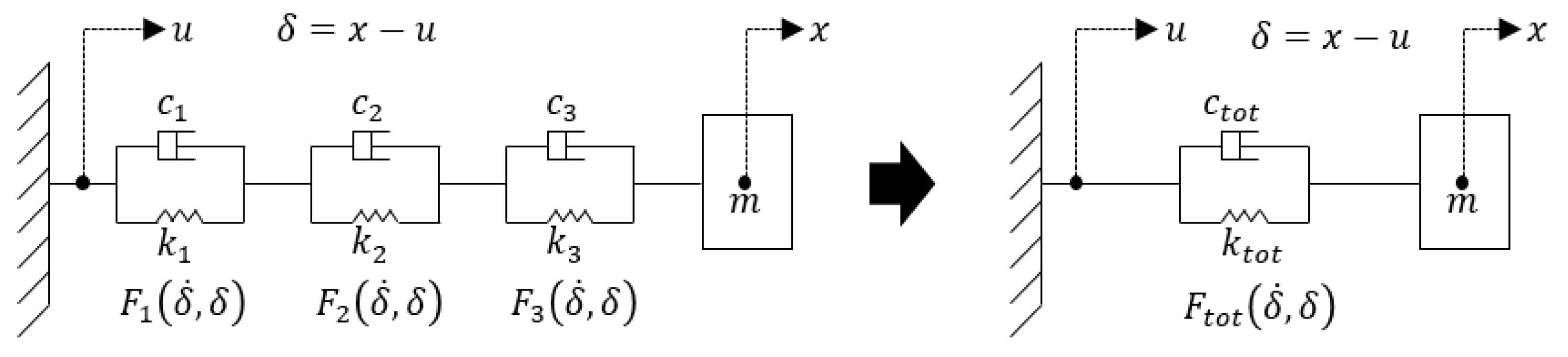
3. Design of Isolator for Reducing Pyro-Shock
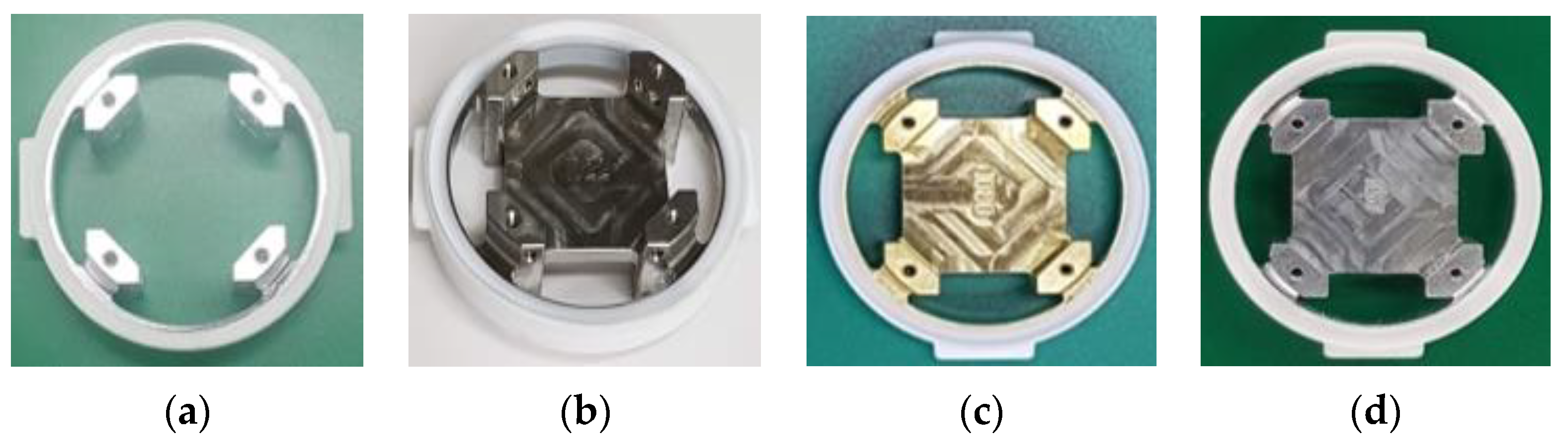
3.1. Improvement Process of Isolator
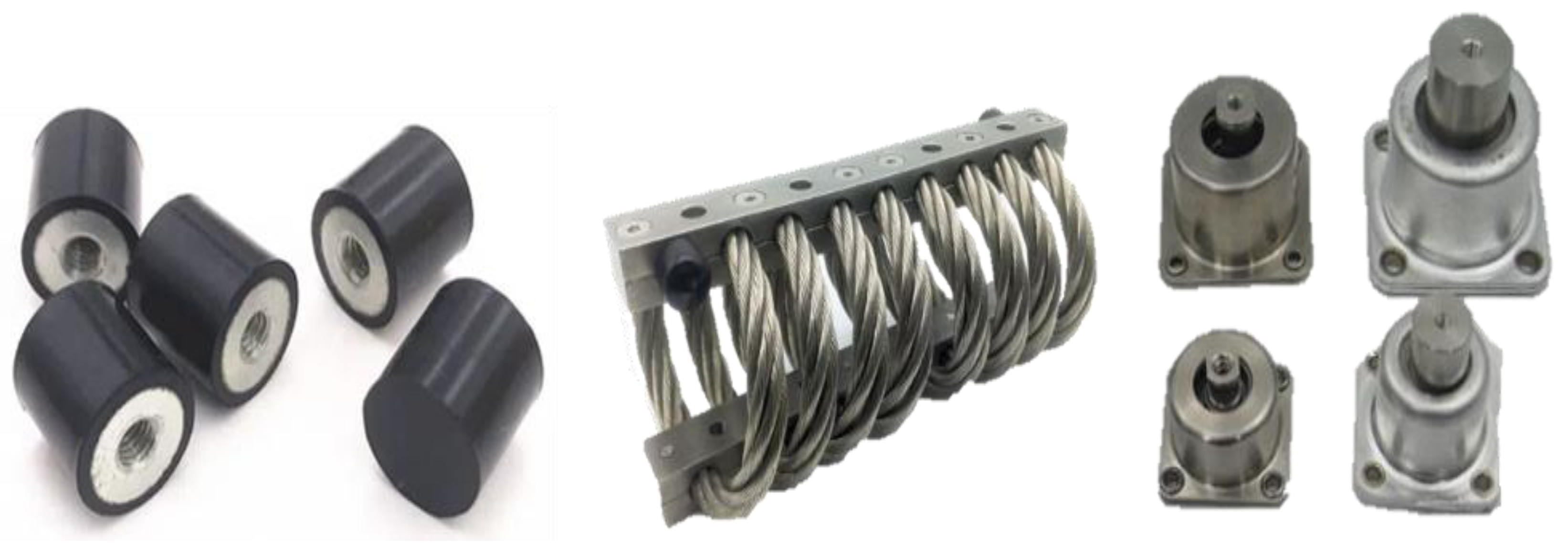
3.1.1. Four-Point Fixed Isolator
3.1.2. SS Integrated Isolator
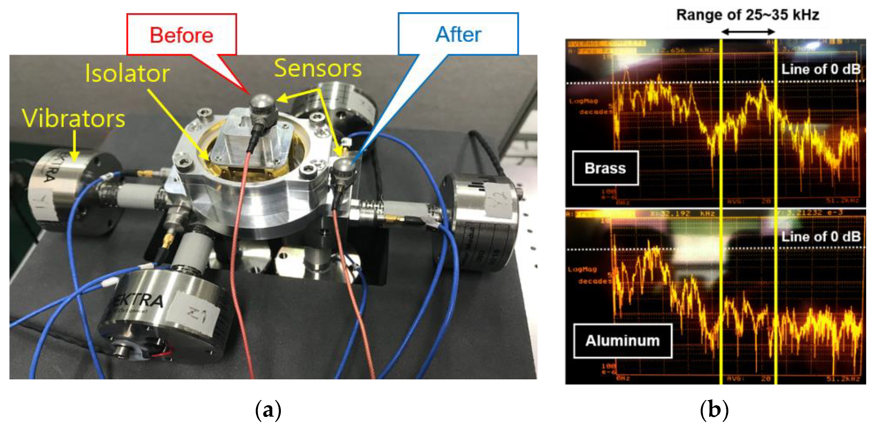
3.1.3. Brass Integrated Isolator
3.1.4. Aluminum Integrated Isolator
4. Mounting Method for Reducing Pyro-Shock
4.1. Description of the Four Mounting Methods
4.2. Multi-Layered (PEEK-Steel-PEEK) Isolator
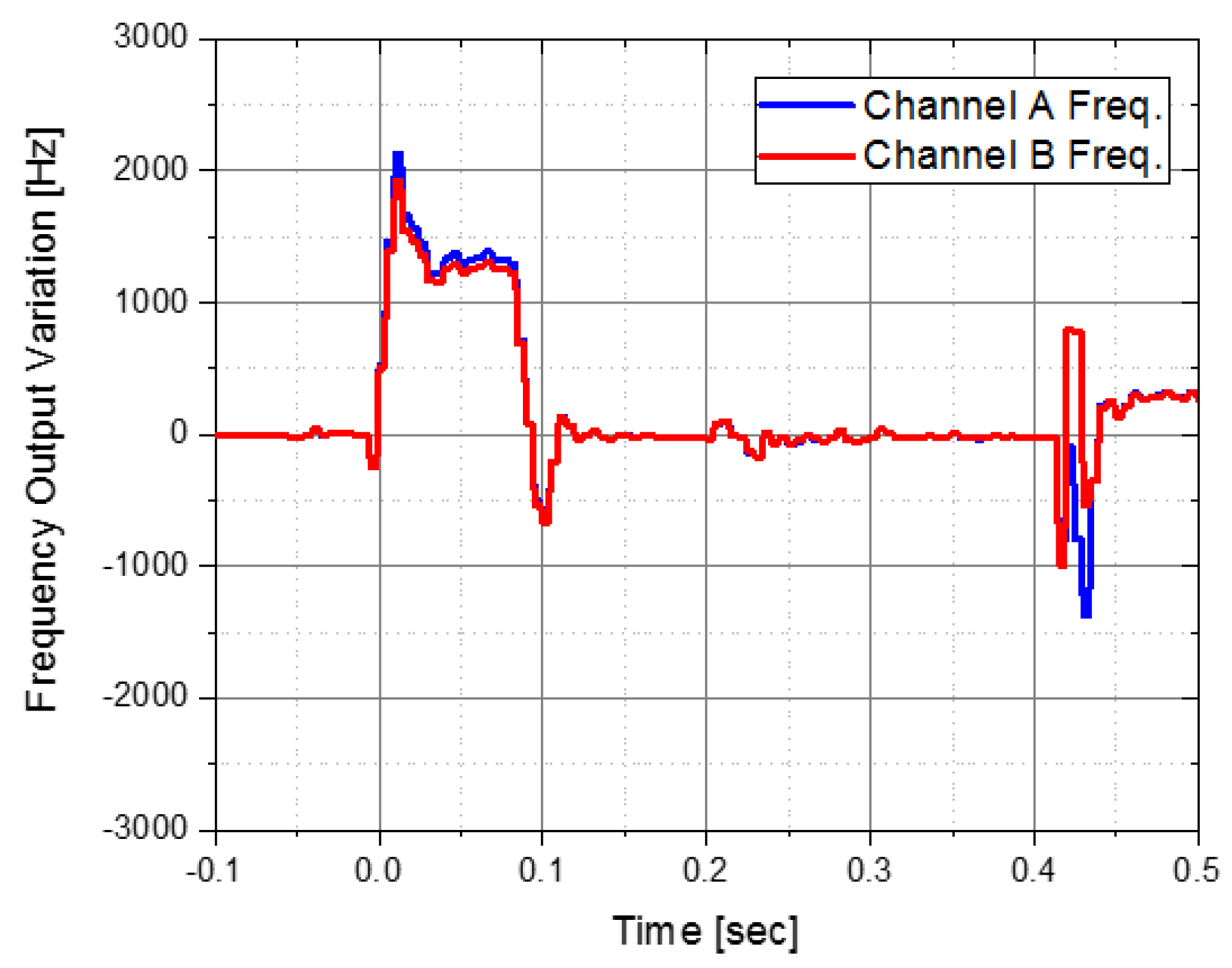
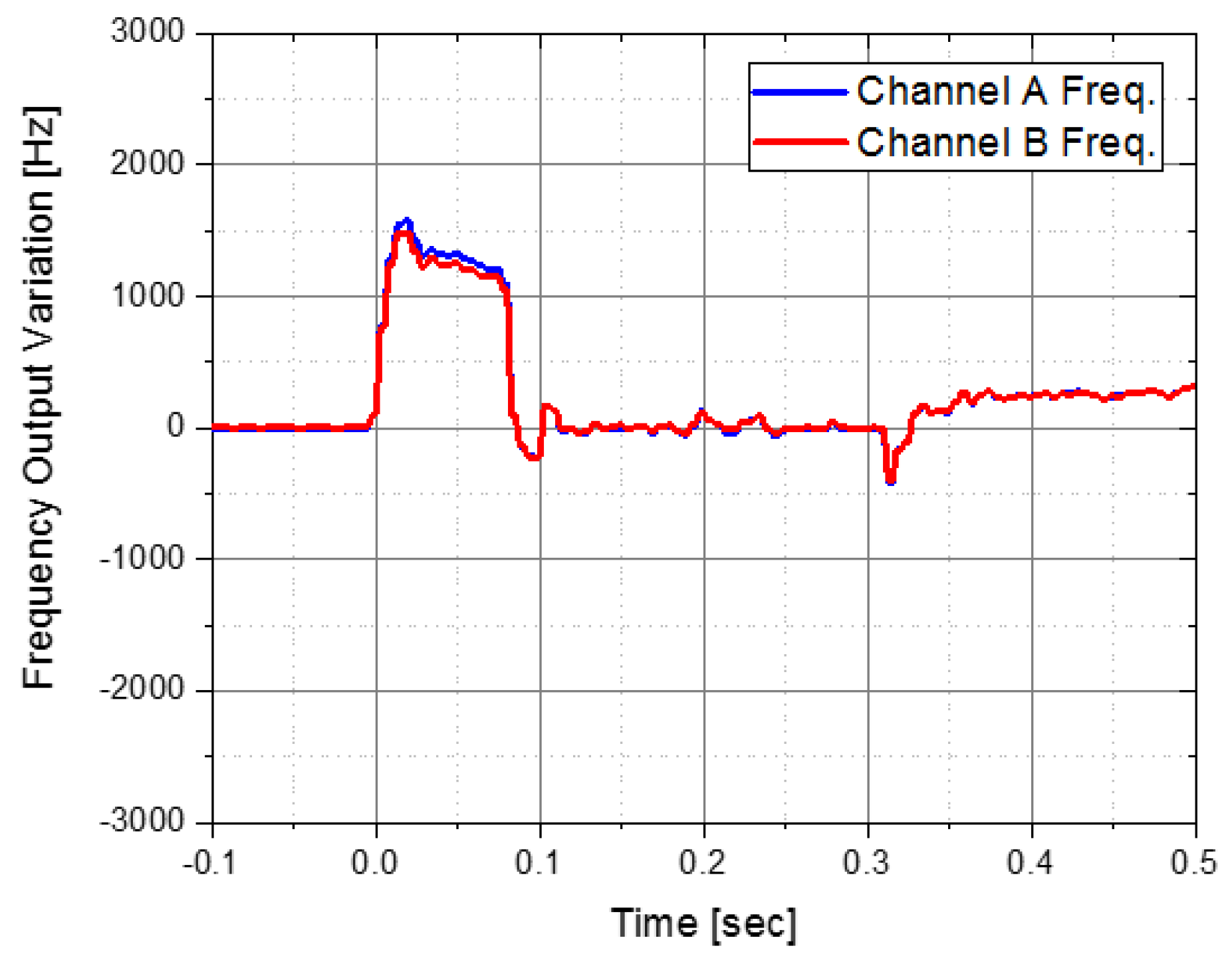
4.3. Reduction Effect Analysis through Pyro-Shock Test
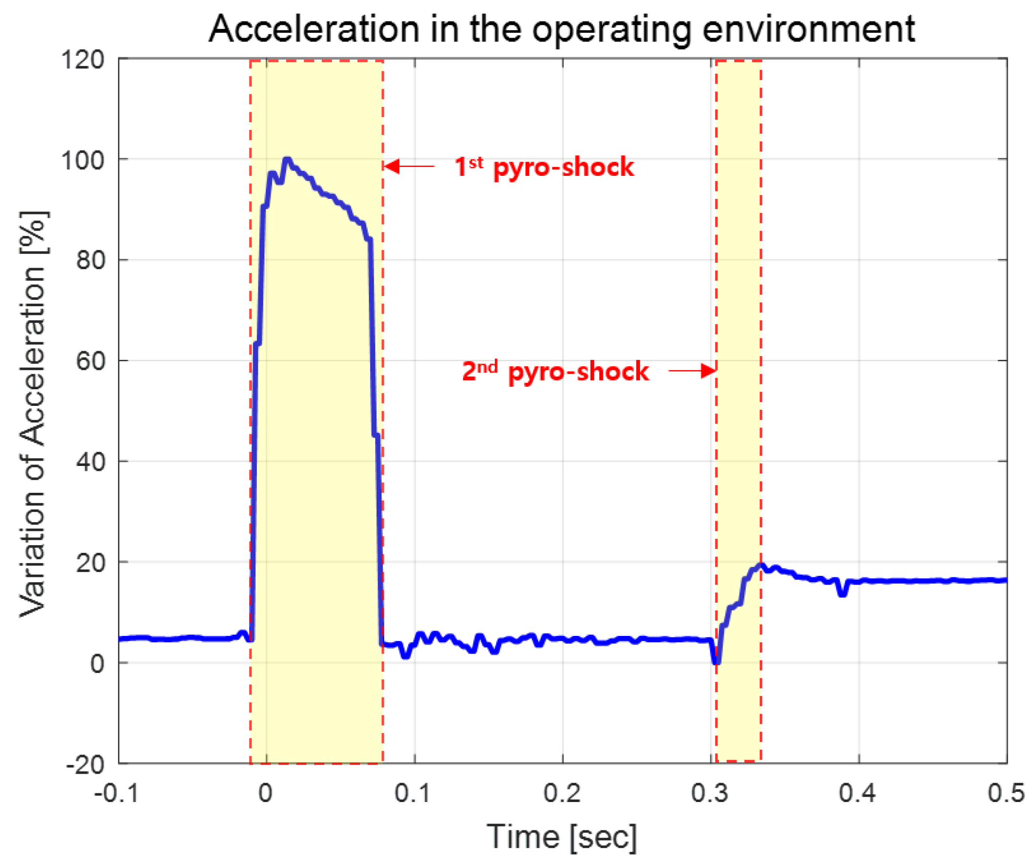
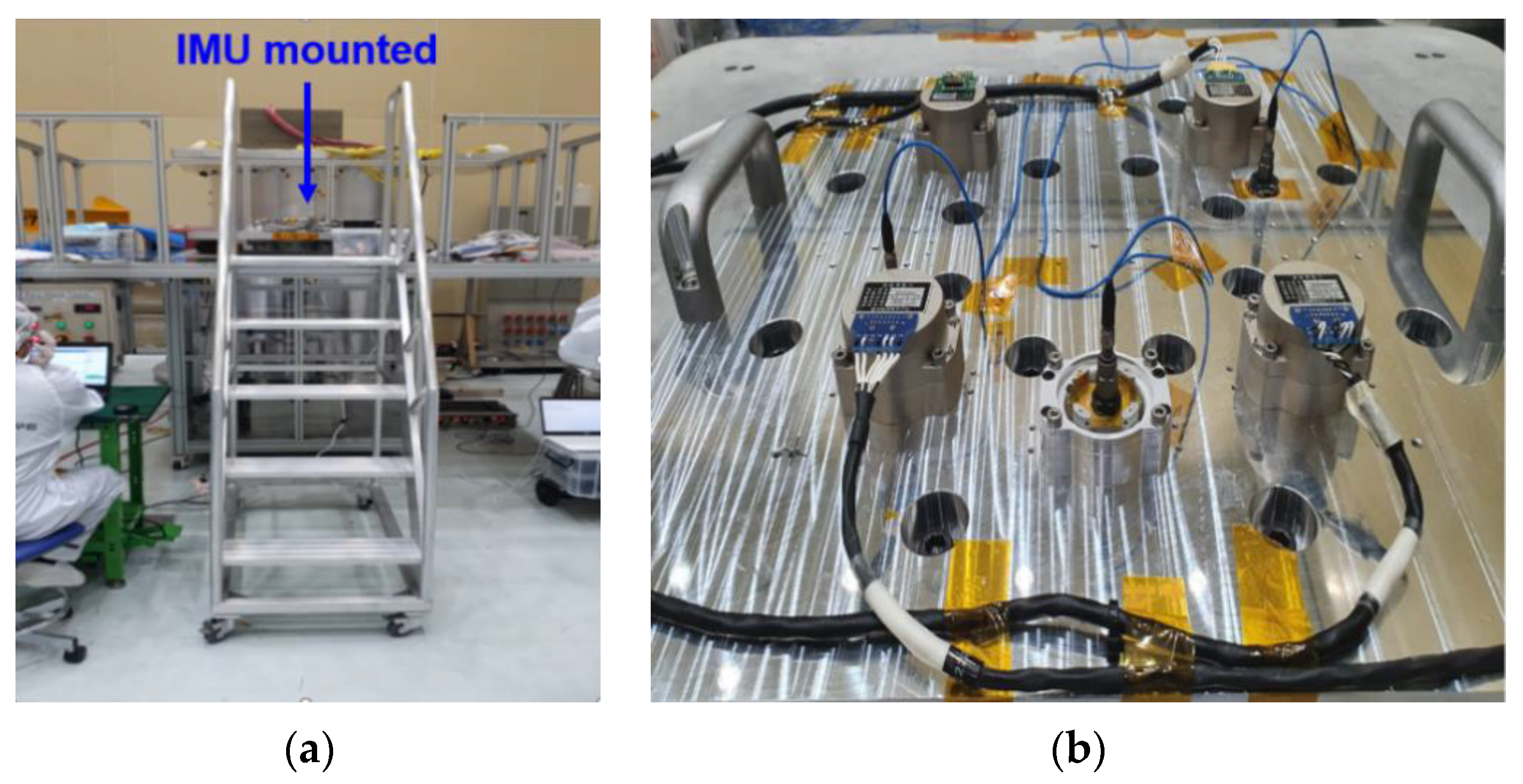
4.3.1. Environment
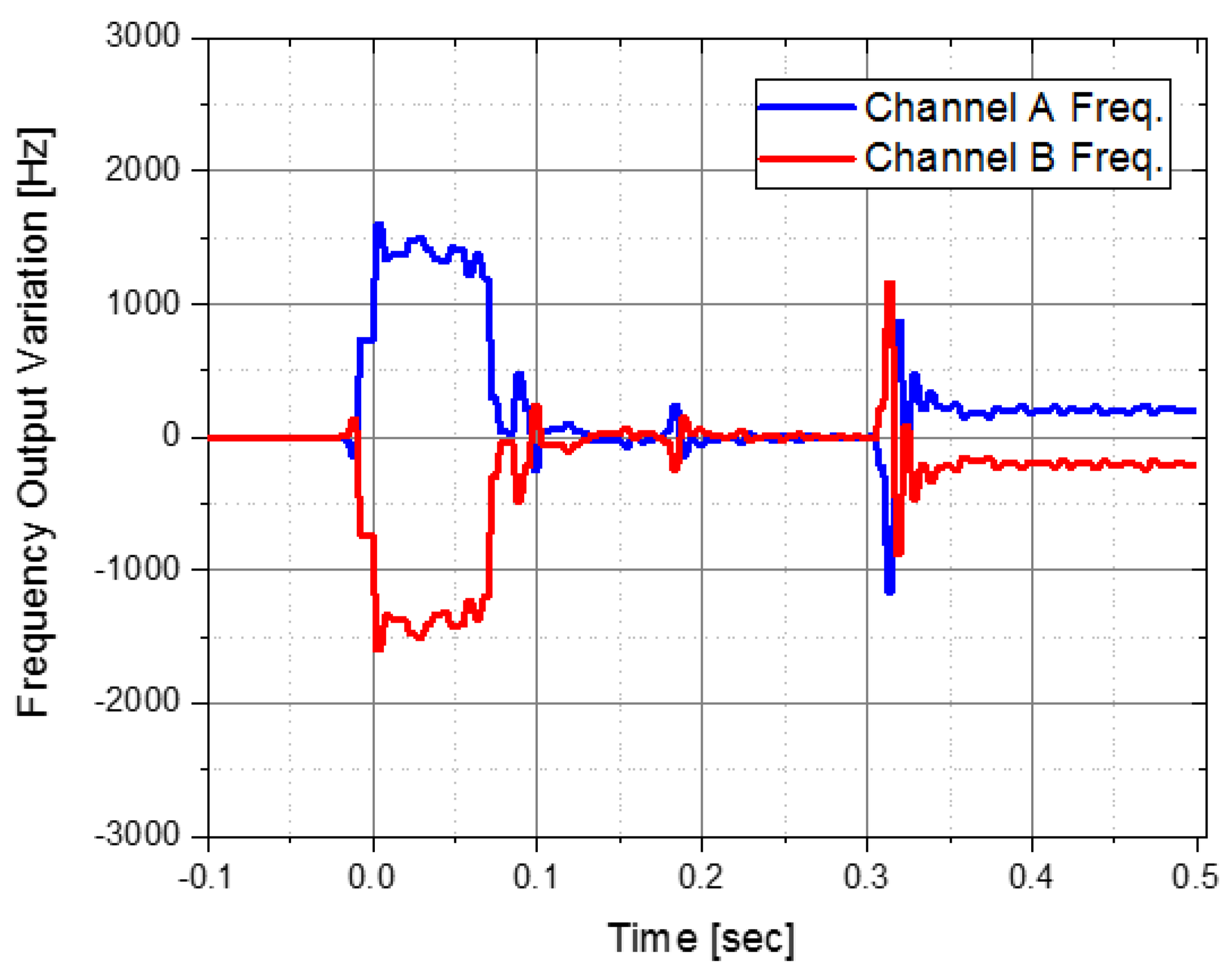
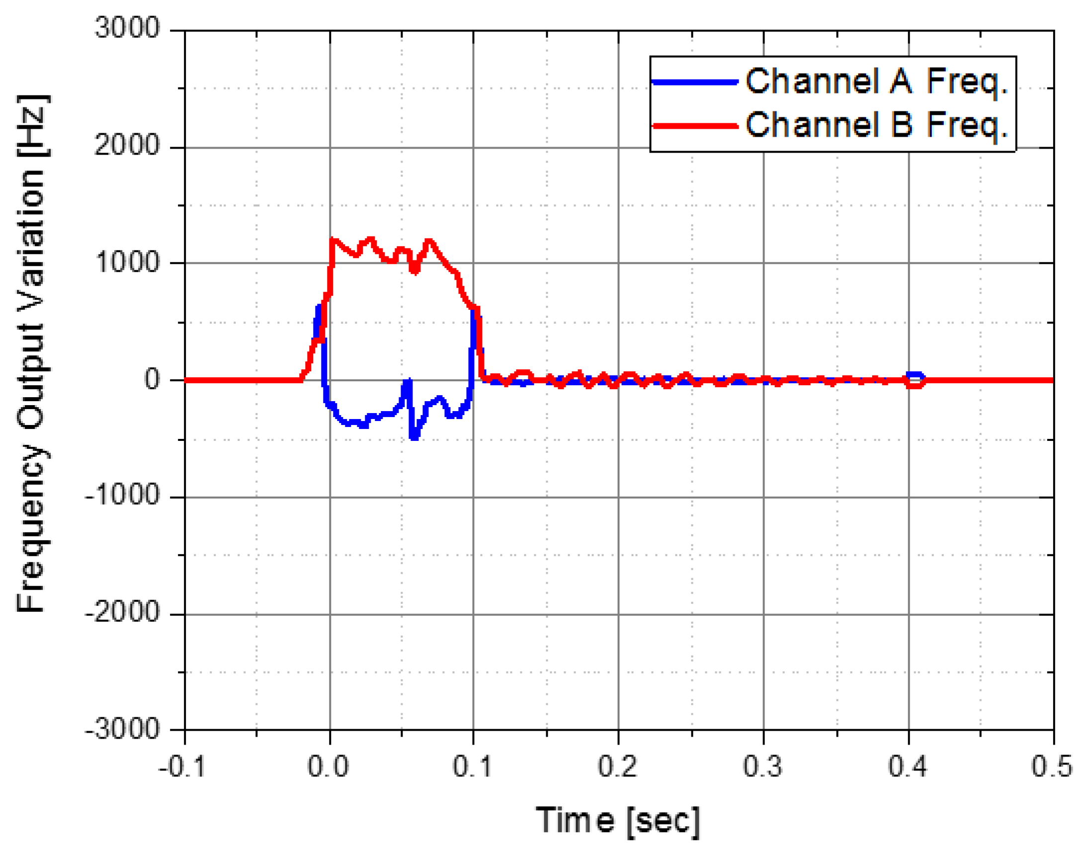
4.3.2. Results
5. Conclusions
Author Contributions
Funding
Conflicts of Interest
References
- Brown, T.G. Harsh military environments and microelectromechanical (MEMS) devices. In Proceedings of the SENSORS IEEE, Toronto, ON, Canada, 22–24 October 2003. [Google Scholar]
- Dean, R.N.; Castro, S.T.; Flowers, G.T.; Roth, G.; Ahmed, A.; Hodel, A.S.; Grantham, B.E.; Bittle, D.A.; Brunsch, J.P. A characterization of the performance of a MEMS gyroscope in acoustically harsh environment. IEEE Ind. Electron. 2011, 58, 2591–2596. [Google Scholar] [CrossRef]
- Singh, V.; Kumar, V.; Saini, A.; Khosla, P.K.; Mishra, S. Response analysis of MEMS based high-g acceleration threshold switch under mechanical shock. Int. J. Mech. Mater. Des. 2021, 17, 137–151. [Google Scholar] [CrossRef]
- Park, B.; Han, K.; Lee, S.; Yu, M. The Extraction Method for the G-sensitivity Scale-Factor Error of a MEMS Vibratory Gyroscope Using the Inertial Sensor Model. J. KSAS 2019, 47, 438–445. [Google Scholar]
- Park, B.; Park, S.; Lee, S. Analysis on the Performance of a MEMS Inertial Measurement Unit under Flight Vibration Using a Roller Coaster. In Proceedings of the 20th Korean MEMS Conference, Jeju Island, Korea, 5–7 April 2018. [Google Scholar]
- Park, B. A Study on the G-sensitivity Error of MEMS Vibratory Gyroscopes. KIEE 2014, 63, 1075–1079. [Google Scholar] [CrossRef] [Green Version]
- Srikar, V.T.; Senturia, S.D. The reliability of microelectromechanical systems (MEMS) in shock environments. J. Microelectromechanical Syst. 2002, 11, 206–214. [Google Scholar] [CrossRef]
- Park, B.; Lee, S.; Han, K.; Yu, M.; Chang, B. Response characteristics of a MEMS resonant accelerometer to external acoustic excitation. In Proceedings of the 2016 IEEE SENSORS, Orlando, FL, USA, 30 October–3 November 2016. [Google Scholar]
- Michael, P.; Robin, L. High-performance low cost inertial MEMS: A market in motion. In Proceedings of the 2012 IEEE PLANS, Myrtle Beach, SC, USA, 23–26 April 2021. [Google Scholar]
- Oliver, W. An Introduction to Inertial Navigation; No. UCAM-CL-TR-696; University of Cambridge, Computer Laboratory: Cambridge, UK, 2007. [Google Scholar]
- Syazdi, N.; Ayazi, F.; Najafi, K. Micromachined inertial sensors. Proc. IEEE 1998, 86, 1640–1659. [Google Scholar]
- Comi, C.; Coriglino, A.; Langfelder, G.; Ongoni, A.; Tocchio, A.; Simoni, B. A resonant microaccelerometer with high sensitivity operating in an oscillating circuit. J. Microelectromechanical Syst. 2010, 19, 1140–1152. [Google Scholar] [CrossRef]
- Youn, S.; Jang, Y.; Han, J. Pyroshock and Vibration Characteristics of PEEK Washer Shock Absorbers. J. KSAS 2008, 36, 285–290. [Google Scholar]
- Park, B.; Ryu, K.; Lee, H.; Han, K.; Lee, S. Performance comparison of a MEMS inertial measurement unit mounting methods for reducing Pyro-shock. In Proceedings of the SASE 2021 Spring Conference, Jeju Island, Korea, 28–31 July 2021. [Google Scholar]
- Davie, N.T.; Bateman, V.I. Pyroshock Testing. In Shock and Vibration Handbook, 4th ed.; Harris, C.M., Ed.; McGraw-Hill: New York, NY, USA, 1996; Chapter 26, Part II. [Google Scholar]


| Case | Cross-Section | Description |
|---|---|---|
| #1 |  |
|
| #2 |  |
|
| #3 |  |
|
| #4 |  |
|
| Specification of Pyro-Shock Simulator | |
|---|---|
| Maximum load | |
| Shock area | |
| Natural frequency of top plate | |
| Maximum shock | |
Publisher’s Note: MDPI stays neutral with regard to jurisdictional claims in published maps and institutional affiliations. |
© 2022 by the authors. Licensee MDPI, Basel, Switzerland. This article is an open access article distributed under the terms and conditions of the Creative Commons Attribution (CC BY) license (https://creativecommons.org/licenses/by/4.0/).
Share and Cite
Ryu, K.; Park, B.; Lee, H.; Han, K.; Lee, S. A Study on the Design of Isolator and the Mounting Method for Reducing the Pyro-Shock of a MEMS IMU. Sensors 2022, 22, 5037. https://doi.org/10.3390/s22135037
Ryu K, Park B, Lee H, Han K, Lee S. A Study on the Design of Isolator and the Mounting Method for Reducing the Pyro-Shock of a MEMS IMU. Sensors. 2022; 22(13):5037. https://doi.org/10.3390/s22135037
Chicago/Turabian StyleRyu, Kyungdon, ByungSu Park, Hyungsub Lee, Kyungjun Han, and Sangwoo Lee. 2022. "A Study on the Design of Isolator and the Mounting Method for Reducing the Pyro-Shock of a MEMS IMU" Sensors 22, no. 13: 5037. https://doi.org/10.3390/s22135037