Review

Recent Advances in Transducers for Intravascular Ultrasound (IVUS) Imaging

1
Department of Mechanical and Aerospace Engineering, North Carolina State University, Raleigh, NC 27695, USA
2
Infraredx, Inc., Bedford, MA 01730, USA
3
Department of Cardiology, New York-Presbyterian Queens Hospital, Flushing, NY 11355, USA
*
Author to whom correspondence should be addressed.
Sensors 2021, 21(10), 3540; https://doi.org/10.3390/s21103540
Submission received: 29 March 2021 / Revised: 11 May 2021 / Accepted: 17 May 2021 / Published: 19 May 2021
(This article belongs to the Special Issue Feature Papers in Physical Sensors Section 2020)

Abstract

:
As a well-known medical imaging methodology, intravascular ultrasound (IVUS) imaging plays a critical role in diagnosis, treatment guidance and post-treatment assessment of coronary artery diseases. By cannulating a miniature ultrasound transducer mounted catheter into an artery, the vessel lumen opening, vessel wall morphology and other associated blood and vessel properties can be precisely assessed in IVUS imaging. Ultrasound transducer, as the key component of an IVUS system, is critical in determining the IVUS imaging performance. In recent years, a wide range of achievements in ultrasound transducers have been reported for IVUS imaging applications. Herein, a comprehensive review is given on recent advances in ultrasound transducers for IVUS imaging. Firstly, a fundamental understanding of IVUS imaging principle, evaluation parameters and IVUS catheter are summarized. Secondly, three different types of ultrasound transducers (piezoelectric ultrasound transducer, piezoelectric micromachined ultrasound transducer and capacitive micromachined ultrasound transducer) for IVUS imaging are presented. Particularly, the recent advances in piezoelectric ultrasound transducer for IVUS imaging are extensively examined according to their different working mechanisms, configurations and materials adopted. Thirdly, IVUS-based multimodality intravascular imaging of atherosclerotic plaque is discussed. Finally, summary and perspectives on the future studies are highlighted for IVUS imaging applications.

1. Introduction

Cardiovascular disease (CVD) is a collection of diseases and conditions that affect the heart and blood vessels in the heart and other vital organs, including coronary artery disease (CAD), heart failure, stroke and hypertension [1]. According to the data provided by World Health Organization (WHO), CVDs are the No.1 cause of death globally. In 2016, 17.9 million people died from CVDs, which accounts for 31% of all global death; of these deaths, 85% are due to CAD and stroke. It is expected that this number will rise to 23.6 million by 2030 [2].
Atherosclerosis is an inflammatory disorder characterized by the gradual accumulation of lipid-rich plaque in the arterial wall [3,4]. It has been recognized that atherosclerosis is the dominant common cause of CVDs, such as CAD, myocardial infarction and stroke [5]. Even though the exact mechanism of atherosclerotic plaque development has not been elucidated yet [6,7], it is found that the plaques are formed following the lipid accumulation [8]. After some time, the plaques gradually harden and narrow the arterial lumen, thus restricting the blood flow. During this period, the artery may respond to the plaque progression by dilatation of the arterial wall (i.e., arterial positive remodeling). While the positive remodeling may widen the lumen, continuous growth of the plaque will induce the development of neovessels, leading to the instability of the plaques and finally resulting in the plaque rupture [9]. It has been shown that the rupture of atherosclerotic plaques is the major source of acute coronary syndrome (ACS), a common complication of CAD that describes a group of conditions that suddenly stop or severely reduce blood from flowing to the heart muscles [9]. That means atherosclerosis becomes dangerous when plaques rupture and intraluminal thrombus is formed, limiting or blocking the blood flow [10]. Plaques with a high risk of rupture are usually referred to as vulnerable plaques. A vulnerable plaque is featured with a large lipid-rich necrotic core (lipid pool) that is surrounded by a thin fibrous cap and permeated with intraplaque macrophages (i.e., thin-cap fibroatheroma (TCFA)) [11,12]. Studies have shown that the risk of plaque rupture is inversely related with the thin cap thickness; 95% of plaque rupture occurs with a thin cap thickness of <65 µm [13,14]. Therefore, TCFA is viewed as the precursor lesion of plaque rupture; early assessment of TCFA can help in developing therapeutic and interventional strategies to avoid plaque rupture and manage CAD [15,16].
Nowadays, the gold standard for the diagnosis of atherosclerosis is invasive coronary angiography [17]. In this imaging method, a catheter is applied to inject radiopaque liquid contrast agent into the bloodstream first; the blood vessel abnormalities, such as narrowing and blockage, can then be visible on X-ray image [18]. To evaluate a coronary angiogram image, it is necessary to compare the region of narrowing with adjacent normal vessel segments. However, there may be a consequent underestimation of the degree of stenosis if the reference region is diffusely narrowed [19]. Even though invasive coronary angiography shows the advantages, such as locating luminal irregularities with high spatial resolution (~100 µm), and real-time assessment, coronary angiography is a 2D luminogram that cannot provide information about the vessel wall and plaque characteristics [20].
Over the past two decades, various invasive and non-invasive imaging modalities have been introduced and validated to comprehensively identify the structure and composition of atherosclerotic plaques [21]. The invasive imaging modalities include intravascular ultrasound (IVUS) imaging, optical coherence tomography (OCT), near-infrared spectroscopic (NIRS) imaging, intravascular photoacoustic (IVPA) imaging, near infrared fluorescence (NIRF) imaging, time resolved fluorescence spectroscopic (TRFS) imaging and fluorescence life-time imaging (FLIM). The non-invasive imaging modalities include computed tomographic coronary angiography (CTCA), magnetic resonance imaging (MRI) and positron emission tomography (PET). Compared to non-invasive imaging modalities, invasive imaging modalities demonstrate higher spatial and temporal resolutions, which allows for better visualization of luminal stenosis and plaque characteristics. Moreover, most of invasive imaging modalities can provide a real-time assessment of the coronary arteries, whereas non-invasive imaging modalities such as CTCA and MRI require relatively long time of imaging processing [19]. Therefore, the invasive imaging modalities are more popular for assessing the severity of CAD and guiding treatment strategies.
Even though several other invasive intravascular imaging modalities are now available, IVUS imaging so far is the most favorable imaging modality for coronary artery assessment [22,23]. Compared with other intravascular imaging modalities, IVUS imaging provides sufficient spatial resolution and penetration depth for precisely visualization coronary artery anomalies. Moreover, the IVUS images provide real-time cross-sectional view of the arterial wall, including morphological and pathological characteristics [24,25]. In addition to identifying plaque vulnerability features, IVUS imaging has long been validated in clinical without any known short-term and long-term side effects [26].
As one of the most crucial components of an IVUS system, ultrasound transducers produce and detect high-frequency ultrasonic waves for real-time high-resolution imaging. In this review, we aim to extensively examine the recent advances in ultrasound transducers for IVUS imaging applications. Firstly, a fundamental review of IVUS imaging principle, evaluation parameters and IVUS catheters are presented. Then, different types of ultrasound transducers for IVUS imaging are summarized. Particularly, the recent advances in piezoelectric ultrasound transducer for IVUS imaging are extensively examined. Thirdly, IVUS-based multimodality intravascular imaging of atherosclerotic plaque is reviewed. Finally, a summary is presented with perspectives on the future directions for IVUS imaging applications.

2. Intravascular Ultrasound (IVUS) Imaging

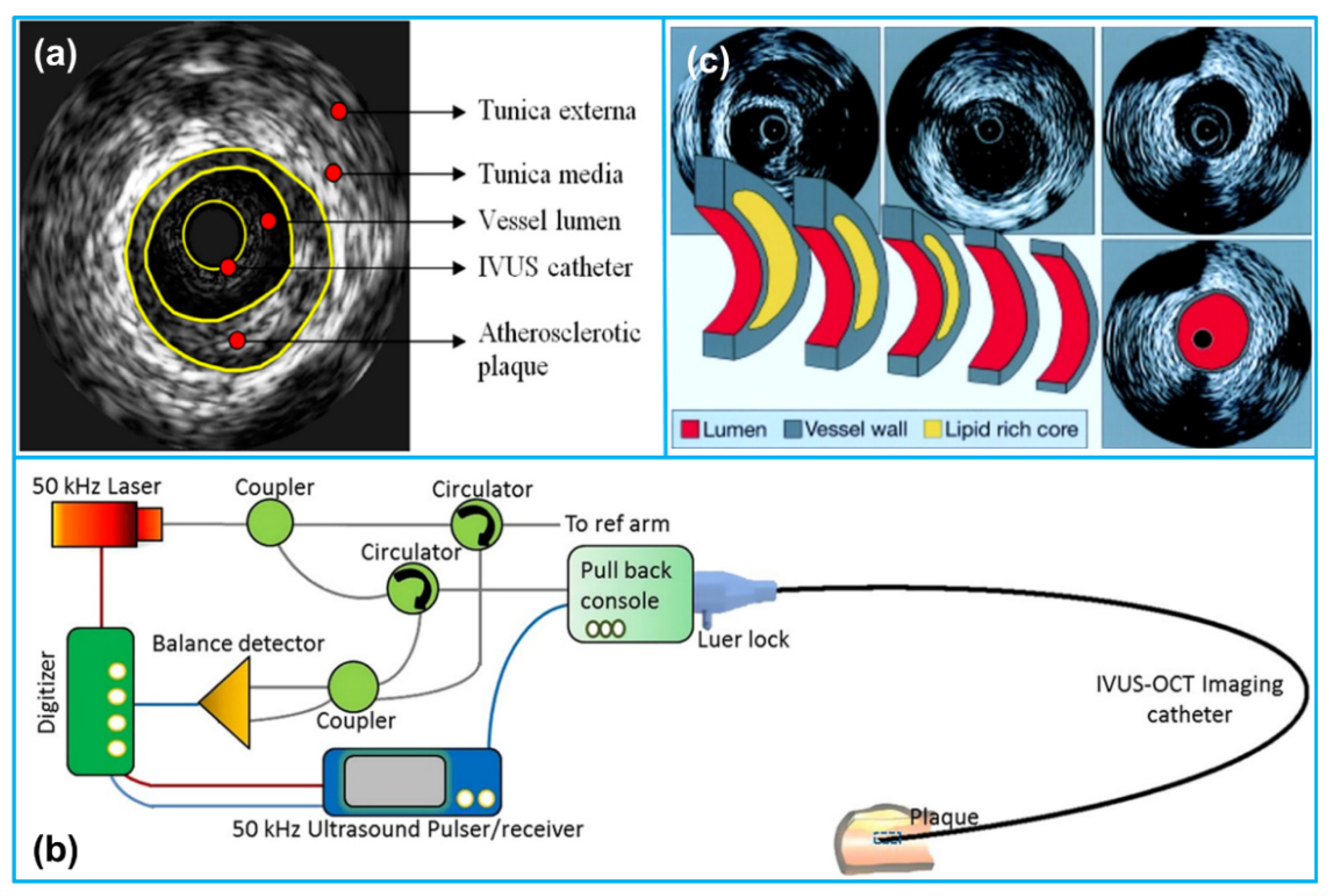
2.1. IVUS Imaging Principle

IVUS imaging is an interventional imaging modality that utilizes reflected ultrasound signals to generate high-resolution images of vascular structures. Similar to many other forms of ultrasound imaging, IVUS images are obtained based on the varying acoustic impedance at the interface of different tissue structures. Specifically, the healthy coronary artery wall mainly consists of three layers, including the inner tunica intima, the muscular tunica media and the outer tunica adventitia (Figure 1a) [27]. Atherosclerotic plaque is formed in the inner tunica intima, which has less echogenicity than the highly echo-reflective outer tunica adventitia [28]. However, thin cap fibroatheromas (TCFA) possessing the majority of atherosclerotic lesions demonstrate moderate echogenicity. Since the tunica media that mainly consists of smooth muscle cells does not reflect ultrasound waves, it appears dark in the grayscale ultrasound image, permitting easy identification of the three layers.
An IVUS imaging system usually consists of three major components: a catheter incorporating a small ultrasound transducer or an array, an imaging console including the necessary hardware and software to convert the acquired IVUS signals to images, and a pullback device to withdraw the catheter in the models with auto-pullback system (Figure 1b) [29]. During IVUS imaging, an IVUS catheter with a tiny transducer at its distal end is advanced over a guidewire beyond the target lesion. Once the catheter is in place, the ultrasound transducer is electrically activated and high frequency ultrasound waves, typically centered at 20–60 MHz, are emitted and propagate into different tissues [30]. A pullback of the transducer tip through the lesion or segment of interest is then performed at a speed of 0.5–2.0 mm/s using the automatic pullback device [31]. The continuously acquired reflection signals from the arterial wall will be utilized to generate a series of tomographic images of the vessel wall (Figure 1c). For example, using a typical pullback speed of 0.5 mm/s and an imaging frame rate of 30 images/s, 60 grayscale images will be obtained from a pullback through a 1 mm segment. Compared with auto-pullback, manual pullback is currently more commonly used, which provides the operator with the opportunity to focus on specific areas of vascular wall more carefully.
Even though grayscale IVUS imaging enables real-time, high-resolution tomographic assessment of atherosclerosis in vivo, delineating plaque area and distribution as well as lesion length based on the comparison of the echogenicity of the plaque to its surrounding adventitia [34], it is limited with regard to quantitative assessment of the plaque composition within a lesion. For instance, both dense fibrotic and calcified tissues in plaques have strong echo-reflections and are thus difficult to differentiate based on grayscale IVUS imaging. In recent two decades, various mathematical methods have been developed to post-process the radiofrequency (RF) backscatter signal, which can generate sophisticated images of atherosclerotic tissue composition. Clinically, there are three different kinds of modes that are used for IVUS RF signal analysis, including virtual histology-IVUS (VH-IVUS) (Volcano Therapeutics Inc., Rancho Cordova, CA, USA), iMapTM IVUS (Boston Scientific Corp., Marlborough, MA, USA), integrated backscatter IVUS (IB-IVUS) (YD Co., Ltd., Nara, Japan) [35]. A summary of the IVUS and IVUS-based imaging modalities is presented in Table 1.
VH-IVUS is the first commercially available RF signal-based tissue composition analysis tool and is the most widely applied in clinical practice nowadays [35]. VH-IVUS is based on the spectral analysis of the raw backscattered IVUS RF data. A mathematical autoregressive model is adopted to analyze the backscattered RF data; tissue color-coded maps are constructed, which classify plaque into four major categories, including fibrous tissue (green), fibro-fatty (light green), necrotic core (red) and dense calcium (white) [36]. Currently, VH-IVUS can be implemented with either a 20 MHz, 2.9 Fr phased-array transducer catheter or a 45 MHz, 3.2 Fr rotational catheter [22]. iMapTM IVUS utilizes a pattern recognition algorithm to process the spectra of the raw backscattered RF signals that are obtained from a fast Fourier transformation. The tissues are color-coded as four major types, including fibrotic (light green), lipidic (yellow), necrotic (pink) and calcified (blue). IB-IVUS is also based on analyzing the RF signals via a fast Fourier transformation. The color code for tissue types is fibrosis (light green), dense fibrosis (yellow), lipid (blue) and calcified (red). Details about the concept, imaging procedures and applications of different IVUS RF signal-based imaging modalities can be found elsewhere [22,23].

2.2. Evaluation Parameters for IVUS Imaging
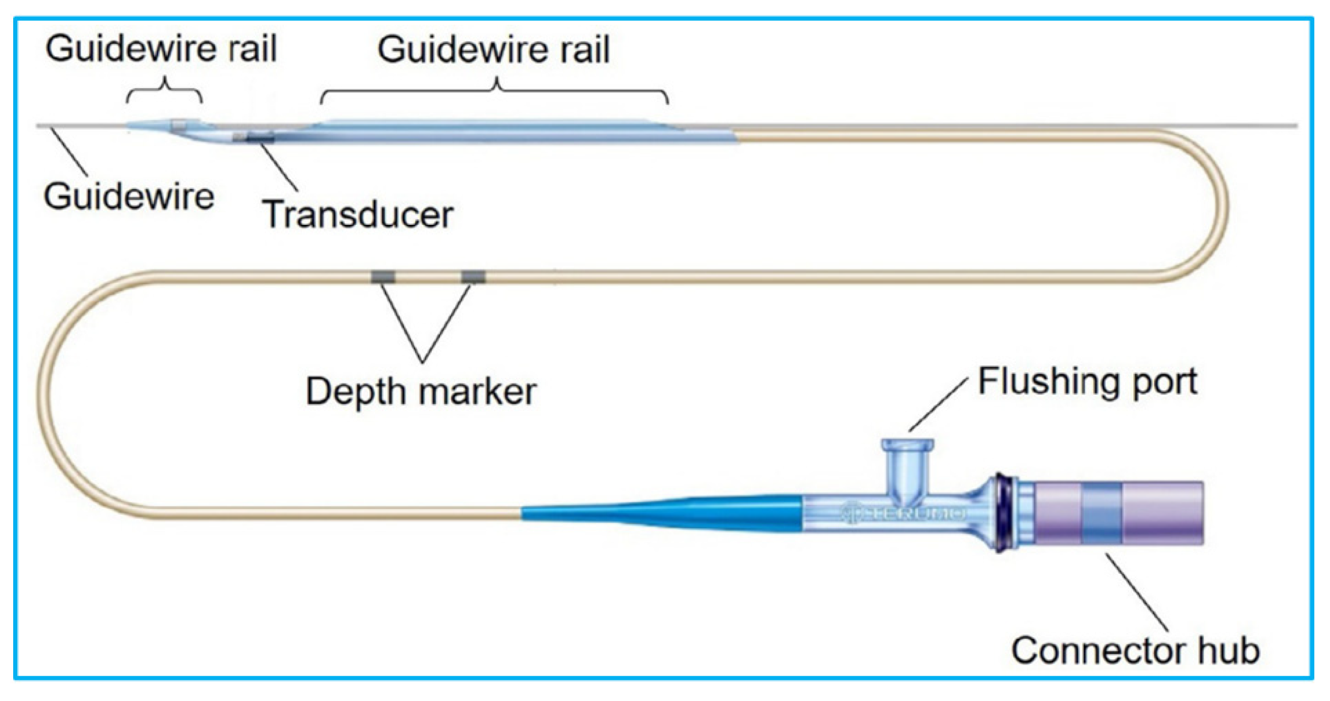
To evaluate IVUS image quality, three critical factors should be typically taken into consideration, which are spatial resolution, imaging sensitivity and image contrast.
The spatial resolution of an ultrasound image is defined as the minimum distance between two adjacent features that can be differentiated [37]. The higher the spatial resolution, the smaller the distance which can be distinguished. Since the 2D cross-sectional ultrasound image displays both depth into the vessel wall and width across a segment of interest, spatial resolution is further subcategorized into axial resolution and lateral resolution. Axial resolution, also known as depth or longitudinal resolution, is characterized as the capacity to differentiate closely adjacent features along the axis of the ultrasound beam, which can be estimated using [38]
R a x i a l = c 2 f c B W = λ 2 B W
where c is the speed of sound, fc is the ultrasound transducer center frequency, BW is the −6 dB fractional bandwidth of the ultrasound transducer, λ is the wavelength. The typical axial resolution ranges ~70–200 µm for 20–50 MHz ultrasound transducers [39].
Lateral resolution is characterized as the capability to distinguish adjacent features in the direction perpendicular to the propagation direction of the ultrasound beam, which can be estimated as [38]
R l a t e r a l = c F # f c = λ F #
where F # represents the f-number, defining as the ratio of focal length to the aperture size of the ultrasound transducer. For an unfocused transducer, the natural focal length F n calculated using Equation (3) can be used to evaluate lateral resolution [40]:
F n = D 2 4 λ
where D is the diameter of the ultrasound transducer. It should be noted that Equation (2) represents the lateral resolution at the focal point and the lateral resolution will downgrade in the off-focus region. For the commonly used IVUS imaging system with transducer frequency ranging 20–50 MHz, the lateral resolution is ~200–250 µm [39].
Another critical image quality index is IVUS imaging sensitivity, which is usually represented by signal-to-noise ratio (SNR), illustrating the capability to detect an ultrasound echo above the background electrical and thermal noise [41].
S N R = 20 log 10 V t i s s u e V n o i s e
where V t i s s u e is the acoustic signal received from an echogenic region of interest; V n o i s e is the signal received when no ultrasound wave is being transmitted (i.e., an anechoic region). It is noted that SNR is a function of imaging penetration depth. With the increase of imaging penetration depth, due to the acoustic attenuation resulting from both scattering and absorption, less acoustic energy will be reflected, causing SNR to decrease. In addition, since the acoustic scattering and absorption increase with the ultrasound frequency, lower SNR is usually expected at higher frequency. For the IVUS applications, the imaging penetration depth is defined as the depth at which SNR falls below 6 dB. The penetration depth of the existing IVUS system is ~6–12 mm [39].
Image contrast represents the capability to distinguish between a feature of interest and the surrounding tissue signals, which is computed using [42]
C R = | μ T μ B | σ T 2 + σ B 2
where μ T and μ B are the acoustic signal magnitude in the target and background regions, respectively; σ T and σ B are the standard deviation of the signal magnitude in each region. Ultrasound image contrast originates from the acoustic impedance differences within the region of interest. It is particularly critical for small features that requires great contrast to be visible against the background speckle.
Other factors that may be used to evaluate an IVUS imaging system include manual versus auto-pullback, IVUS imaging and fluoroscopic angiography co-registration, etc. [43], which are not included in this review since they are not closely related with the IVUS transducer performance.

2.3. IVUS Catheter

The IVUS catheter is a thin, flexible tube with a miniature transducer mounted on the distal end to image the interior of blood vessels (Figure 2). The proximal end of the catheter connects to a workstation that converts the reflected ultrasound waves from the vessel walls into real-time images to display on a monitor. To conduct IVUS imaging, an IVUS catheter is fed over a guidewire first and angiography is used to guide the catheter to the region of the vessel to be imaged. The IVUS transducer is placed either distal to the region to be imaged and then pulled back through the region of stenosis, or directly placed at the interested area for image acquisition [44].
In the USA, there are two major manufacturers with FDA-cleared IVUS systems, which are Boston Scientific and Philips (after acquisition of Volcano Therapeutics in 2015) [25]. Other top manufacturers include Terumo (Somerset, NJ, USA), Infraredx (Burlington, MA, USA) and ACIST Medical Systems (Eden Prairie, MN, USA). The commercially available IVUS catheters from different manufacturers are listed in Table 2. The catheter sizes range from 2.6–3.5 Fr (0.87–1.17 mm) and can be easily guided through a 5–6 Fr femoral sheath [46]. The typical length of the IVUS catheters is 150 cm and can be used to visualize over 15 cm of a coronary artery. The imaging field of the catheters is about 20 mm, which is sufficient for coronary arteries (average diameter 4–5 mm) imaging [47].

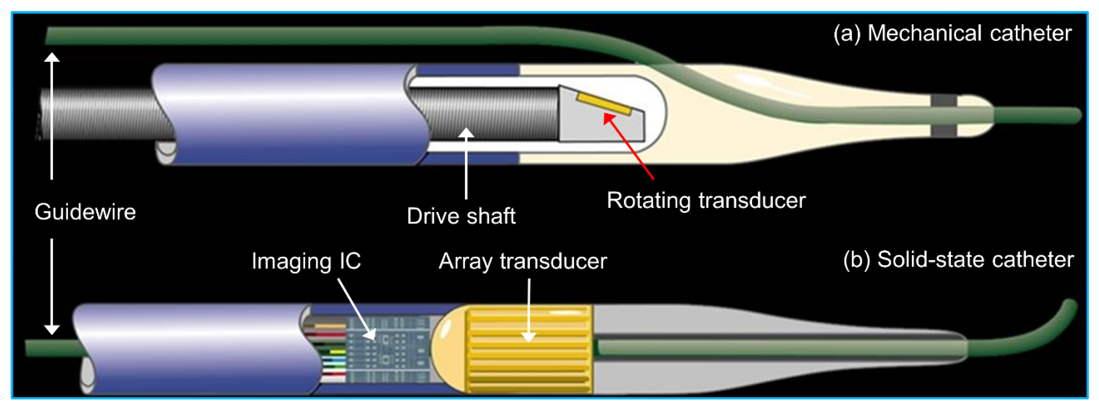
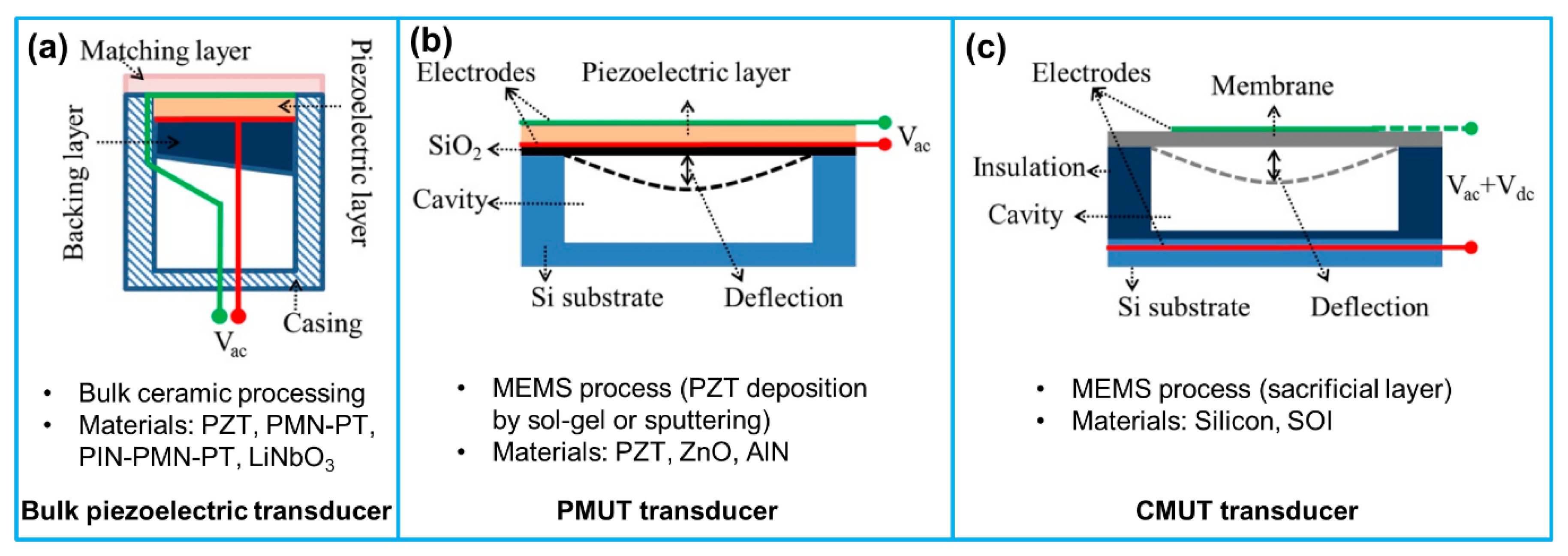
2.4. Ultrasound Transducers for IVUS Imaging

Currently, there are two types of catheters based on the ultrasound transducer structures implemented, which are mechanical/rotational catheter and solid-state catheter (Figure 3) [48]. Both types of catheters can generate a 360° cross-sectional image plane perpendicular to the catheter tip. The major difference between them is the ultrasonic wave transmitting and receiving modes [49]. In the mechanical/rotational catheter, a single-element ultrasound transducer is mounted at the tip of a flexible drive shaft housed in a protective sheath; an external motor drive attached to the proximal end of the catheter rotates the transducer at a speed of 1800 revolutions/min via spinning the drive cable; the transducer transmits and receives the ultrasonic waves at 1° increment to synthesize a cross-sectional image of the vessel [50]. In the solid-state catheter, no rotating components are present. A phased array transducer with 64 transducer elements is mounted circumferentially around the tip of the catheter. The transducer elements are sequentially activated by the integrated circuit in the catheter tip with different time delays to generate an ultrasonic beam that sweeps the circumference of the vessel. The reflected ultrasonic signals from each segment of the vessel wall are collected to reconstruct the cross-sectional image [51]. The comparison of these two types of catheters is shown in Table 3. The most powerful advantage of a solid-state catheter over a mechanical/rotational catheter is that electrical scanning allows for stable imaging, which makes it possible for accurate speckle analysis, and flow analysis and palpography in IVUS imaging.
Four different categories of ultrasound transducers have been reported for IVUS imaging: conventional piezoelectric ultrasound transducer, piezo-composite micromachined ultrasound transducer (PC-MUT), piezoelectric micromachined ultrasound transducer (PMUT) and capacitive micromachined ultrasound transducer (CMUT) (Figure 4) [52,53,54]. The details about structures and fabrication processes of these four types of ultrasound transducers have been reported by many references. Interested readers are referred to the cited references [52,53,55,56,57].
Until now, due to the mature fabrication techniques, piezoelectric ultrasound transducers dominate the market of IVUS catheters [54]. Based on the different applications (mechanical/rotational catheter and solid-state catheter), they can be categorized into two types: single element and phased array. The most commonly utilized piezoelectric material for the ultrasound transducer is lead zirconate titanate (PZT) ceramics, having a high electromechanical coupling coefficient. Other materials, such as lead magnesium niobate-lead titanate (PMN-PT) single crystals and lead indium niobate-lead magnesium niobate-lead titanate (PIN-PMN-PT) single crystals, that have even higher electromechanical coupling coefficient have also been used for fabricating broadband IVUS transducers. One of the major concerns of these lead-based piezoelectric materials is that they may be harmful to human health for IVUS imaging applications. While some lead-free piezoelectric materials, such as potassium sodium niobate (KNN), have also been adopted by researchers for IVUS transducers, their inferior acoustic and electrical properties make them almost impossible to surpass lead-based materials [58,59]. Since the piezoelectric material-based ultrasound transducer is the mainstream nowadays, the advancement of piezoelectric transducers for IVUS imaging applications will be comprehensively examined in the following section.
Compared with conventional piezoelectric ultrasound transducers, PMUT demonstrates its uniqueness for IVUS imaging. Contrary to conventional piezoelectric ultrasound transducer, PMUT is compatible with complementary metal oxide semiconductor (CMOS), which means that the fabrication process of PMUT can be easily integrated with supporting electronic circuits. Moreover, PMUT demonstrates small form factor, high capacitance and low electrical resistance. Other advantages include its low sensitivity to parasitic capacitance, low loss and high SNR [60,61]. In 2014, Dausch et al. [62] fabricated two rectangular PMUT arrays containing 256 and 512 active elements for an intracardiac ultrasound catheter, which was operated at 5 MHz. The PMUT arrays were fabricated in silicon-on-insulator substrates using PZT. Based on the 3D ultrasound imaging in a swine model using the fabricated 14 Fr catheter, a frame rate of 26 volumes/sec could be obtained in a 60° × 60° volume sector with 10 cm penetration depth; the frame rate would be increased to 31 volumes/sec while the depth reduced to 8 cm. While this was the first publication about intracardiac echocardiography (ICE), seldom studies have reported PMUTs for IVUS imaging applications. Possible reasons are that the existing fabrication techniques cannot achieve high frequency, and the active materials have low electromechanical coupling coefficient, thus making it difficult to satisfy the bandwidth, resolution and sensitivity requirements for IVUS imaging.
Compared to PMUT, CMUT can achieve higher working frequency and broader bandwidth for IVUS imaging [63]. Furthermore, CMUTs are also CMOS-compatible and have small form factor [64]. Currently, three types of CMUTs have been reported for IVUS imaging applications: cylindrical CMUT array [65], phased CMUT array [66,67,68] and dual-ring CMUT array [69,70,71,72]. Zhuang et al. [65] fabricated a 16 × 16-element flexible 2D CMUT array by using a PDMS trench refilling technique. The array with a size of 4 mm × 4 mm demonstrated a resonant frequency of 4.3–5.0 MHz for DC bias voltage of 70–100 V. Due to the flexibility of the CMUT array, it could be wrapped around a 3 Fr catheter tip for side looking IVUS imaging. Xu et al. [66] designed and fabricated four 12-element 1D CMUT phased arrays for cross-sectional imaging of artery. The CMUT array operated with a resonant frequency of around 40 MHz and an aperture of 0.3 mm × 1.0 mm. Four 90° sector images of the artery were obtained based on the four CMUT arrays configuration. In another study, Gurun et al. [72] developed a dual ring CMUT array with 56 transmit elements and 48 receive elements on two concentric annular rings. The dual ring CMUT array had an outer diameter of 1.5 mm and a center hole diameter of 430 µm for guidewire insertion. Based on the image quality testing at 20 MHz, the array showed axial and lateral resolutions of 92 and 251 µm, respectively. A comparison of IVUS imaging qualities using PMUT and CMUT arrays with that of representative piezoelectric transducers is shown in Table 4. Even though CMUTs have demonstrated large bandwidth and electromechanical coupling coefficient for IVUS imaging, a large voltage bias is necessary for achieving high frequency and large sensitivity operations, which increases the risk of dielectric charging and breakdown of the device [73]. Additionally, due to the different acoustic transmitting and receiving requirements, distinct transmission and reception array structures may be needed, thus complicating the design and fabrication [55].

3. Piezoelectric Transducers for IVUS Imaging

As summarized in Table 2, the currently available commercial IVUS transducers including both single-element transducer and phased array transducer, have a center frequency ranging from 20–60 MHz. This frequency range typically provides an axial resolution of 20–100 µm, a lateral resolution of 150–250 µm and a penetration depth of 6–15 mm for IVUS imaging [38,75]. Even though the existing IVUS catheters operating at this frequency range are able to assess lumen size, thickness of the vessel wall and lesion location [76], their spatial resolutions are insufficient to evaluate the thickness of fibrous cap (typically <65 µm), a major precursor lesion for vulnerable plaque rupture and acute coronary syndromes [77]. In order to achieve better diagnostic accuracy of coronary artery diseases, tremendous effort has been made over the last two decades to improve IVUS imaging performance by increasing transducer frequency, adopting new transducer designs and piezoelectric materials, as well as combining it with other imaging modalities.

3.1. Single Frequency IVUS Transducer

3.1.1. Conventional Piezoelectric IVUS Transducer

Since the IVUS imaging resolution is inversely related to the transducer frequency according to Equations (1) and (2), the most straightforward way to get better imaging resolution is to improve the transducer frequency. Li et al. [78] fabricated an 80 MHz IVUS transducer using a 30 µm-thick PMN-PT free standing film that had high electromechanical coupling coefficient (kt~0.55) and dielectric constant ( ε r / ε 0 ~4364). The miniature transducer with an aperture of 0.4 mm × 0.4 mm illustrated a −6-dB bandwidth of 65%, and axial and lateral resolutions of 35 µm and 176 µm, respectively. However, the 80 MHz IVUS transducer only had a penetration depth of 2 mm, which could not assess the whole depth of vessel wall (typically >5 mm). To make a tradeoff between the imaging resolution and penetration depth, Sung and Jeong [79] fabricated a 60 MHz transducer with an aperture of 0.49 mm × 0.4 mm using PMN-PT single crystal. The transducer showed a −6 dB bandwidth of 60.2%, which resulted in axial and lateral resolutions of 24.8 µm and 156.1 µm, respectively, and a penetration depth of ~5 mm. More recently, according to the three-matching-layer method that can widen the transducer bandwidth, Ma and Cao [80] reported a 45 MHz IVUS transducer with an aperture of 0.4 mm × 0.5 mm using PMN-PT single crystal. The transducer illustrated a −6 dB bandwidth of 61%, axial and lateral resolutions of 41.6 µm and 214.7 µm, respectively, and a penetration depth of 5 mm. Zhang et al. [81] developed a 40 MHz transducer using high performance PNN-PZT ceramic with an aperture of 0.33 mm × 0.33 mm. The transducer exhibited a −6 dB bandwidth of 79%, and axial and lateral resolutions of 36 µm and 141 µm, respectively.
Another commonly used method to improve transducer resolution is to develop a focal geometry. Fei et al. [82] developed a 35 MHz IVUS transducer with a half-concave structure using PMN-PT single crystal. The 1.2 mm × 1.2 mm transducer showed a −6 dB bandwidth of 54%, and axial and lateral resolutions of 34.5 µm and 392 µm, respectively. Yoon et al. [83] fabricated an angle-focused IVUS transducer using PMN-PT single crystal with a viewing angle of 60° and center frequency of 45 MHz. The focused transducer illustrated a −6 dB bandwidth of 72%; the axial and lateral resolutions were calculated as 25 µm and 120 µm, respectively. In another study, Lee et al. [84] developed an oblong shaped focused IVUS transducer using PZT ceramic, having a center frequency of 50 MHz and a focal distance of 3 mm. The 0.5 mm × 1.0 mm oblong shaped transducer showed a −6 dB bandwidth of 57% and a lateral resolution of 150 µm.
While lead-based piezoelectric materials including PZT ceramic, PMN-PT and PIN-PMN-PT single crystal are the most popularly adopted materials for IVUS transducers due to their excellent piezoelectric performance and mature fabrication techniques, the raised health and environment concerns about the toxic lead-based materials have inspired researchers to develop lead-free piezoelectric materials for IVUS transducers [61,85,86]. Yan et al. [87] fabricated a 30 MHz IVUS transducer with an aperture of 0.8 mm × 0.8 mm using lead-free BZT-50BCT ceramic that showed a high ε r / ε 0 of ~2800 and piezoelectric coefficient d33 of ~600 pC/N. The fabricated transducer demonstrated a −6 dB bandwidth of 53%. Zhu et al. [88] utilized 35 µm Li doped KNN (KNLN) thick film for developing a 50 MHz side-looking IVUS transducer, having an aperture of 0.4 mm × 0.4 mm. Similar to lead-based materials, kt of the thick film was 0.44; the fabricated transducer illustrated a −6 dB bandwidth of 61.5%. Fei et al. [89] adopted lithium niobate (LiNbO3) to develop single element transducers with ultrahigh frequencies (100–300 MHz) for super-resolution ultrasound imaging applications. While the axial and lateral resolutions of 15.4 µm and 16.4 µm, respectively could be obtained for the 100 MHz focused transducer, the high attenuation in blood and poor penetration depth have limited its applications in IVUS imaging.

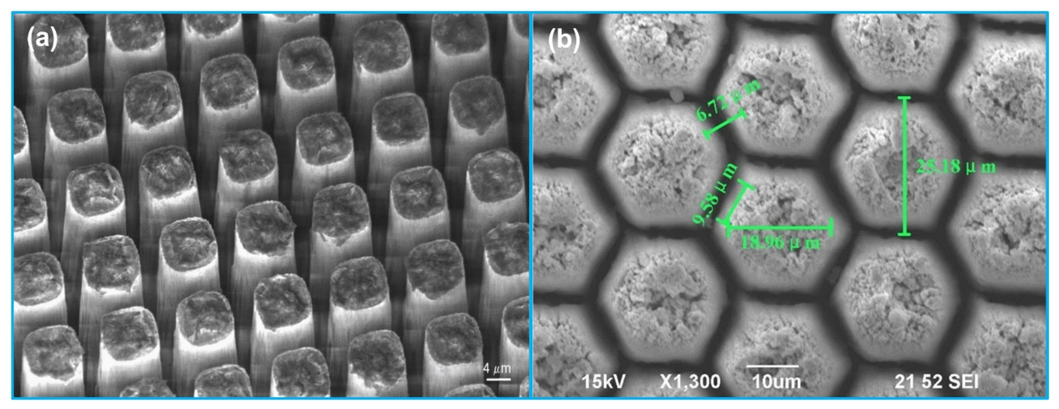
3.1.2. Piezo-Composite Micromachined Ultrasound Transducer (PC-MUT)

An alternative method to improve imaging resolution without sacrificing penetration depth is to develop a transducer with broader bandwidth at relatively lower frequency. Compared with monolithic piezoelectric materials, 1-3 piezo-composite structure can provide broader bandwidth due to its higher kt. Moreover, the acoustic impedance of a piezo-composite is much lower than that of a bulk piezoelectric material, which can significantly reduce the acoustic mismatch between transducer and tissue [52]. However, developing a high frequency 1-3 piezo-composite using the conventional dice-and-fill technique usually provides a low volume fraction, and a large pillar and kerf width to thickness aspect ratio due to the limitation of dicing blade width [90]. The minimum existing blade width is typically 10–15 µm, thus limiting the transducer frequency <20 MHz [52]. In addition, due to the limitation of current dicing capability, the shape of pillars in a 1-3 piezo-composite is squarely distributed. Nevertheless, studies have reported that other shape of pillars such as hexagonal can achieve better electromechanical and acoustic performance [91,92]. In order to overcome the limitations of conventional dice-and-fill method, Jiang et al. [52,93] developed photolithography-based deep reactive ion etching (DRIE) micromachining process for fabricating high frequency 1-3 piezo-composite, namely PC-MUT (Figure 5a). The PC-MUT technology takes advantages of high kt of PMN-PT single crystals, fine patterning features of photolithography and DRIE for fabrication of composite microstructures. Based on the PC-MUT technology, high frequency (20–100 MHz) 1-3 PMN-PT composite transducers with a post width of 12–14 µm, a kerf width of 3–4 µm and a kt of 0.72 were fabricated for IVUS imaging applications [94,95]. Following these works, Li et al. [96] reported a 40 MHz miniature transducer with an aperture of 0.5 mm × 0.4 mm fabricated by PIN-PMN-PT single crystal 1-3 composite. Compared with commonly used piezoelectric materials for an IVUS transducer, such as PZT ceramic and PMN-PT single crystal, PIN-PMN-PT single crystal does not only have high kt and ε r / ε 0 , but also illustrate improved electrical and thermal stability [97,98,99]. Based on the authors’ results, an effective electromechanical coupling coefficient of 0.75–0.78 was obtained; the fabricated 40 MHz transducer demonstrated a −6-dB bandwidth of 86%, resulting in axial and lateral resolutions of 43 µm and 226 µm, respectively.
More recently, a cold ablation process that is based on focused picosecond UV laser is also reported for high frequency 1-3 piezo-composite fabrication (Figure 5b). Since the pulse width of picosecond laser is shorter than the thermal relaxation time, the cold ablation process can be used to remove thin material layers without significant thermal side-effects [100]. Xu et al. [101] fabricated a 45 MHz 1-3 PZT-5H composite using a cold ablation process with a picosecond UV laser. The width of the pillar was 20.5 µm; the kerf of the pillar was 4.5 µm; the fabricated piezo-composite demonstrated a kt of 0.73. In another work, Li et al. [100] fabricated a 50 MHz 1-3 PZT-5H composite with a hexagonal pillar geometry using the cold ablation technique. The kerf width of the 1-3 piezo-composite was 5 µm; the pillar width was 10 µm, showing a PZT-5H volume fraction of 64%. The 1-3 piezo-composite demonstrated a kt of 0.7 and a −6 dB bandwidth of 68.8%.

3.1.3. Micromotor Driven IVUS Imaging

Currently, all the mechanical/rotational IVUS catheters obtain the vessel cross-sectional images via a rotating reflector driven by a proximal motor and a flexible driving shaft [102]. The major limitation of this type of configuration is the image distortion, known as non-uniform rotation distortion (NURD), that occurs when the catheter passes through a bending vessel due to the friction force between the flexible drive shaft and catheter wall [103]. To avoid NURD, a different catheter structure with the driven motor placed on the distal end of catheter has been proposed and developed for IVUS imaging, thus directly rotating an ultrasonic transducer or a miniature reflecting mirror instead of transmitting the rotational motion by a flexible shaft. Peng et al. [103] developed a three-phased synchronous electromagnetic micromotor, which had a dimension of 1.2 mm × 3.7 mm and a maximum rotating speed of 16,500 rpm. At the driving frequency of 10 Hz, the maximum angular error was 4°. In addition to electromagnetic micromotor, piezoelectric micromotor was also reported [104,105,106,107,108]. For example, Zhang et al. [109] designed and fabricated a piezoelectric micromotor with a size of 1 mm × 10 mm and a maximum rotating speed of 6450 rpm. The speed of the micromotor was controllable and the maximum angular error was 8°, which would not cause obvious image distortion.
The imaging performance comparison of the reported single frequency IVUS transducers is summarized in Table 5.

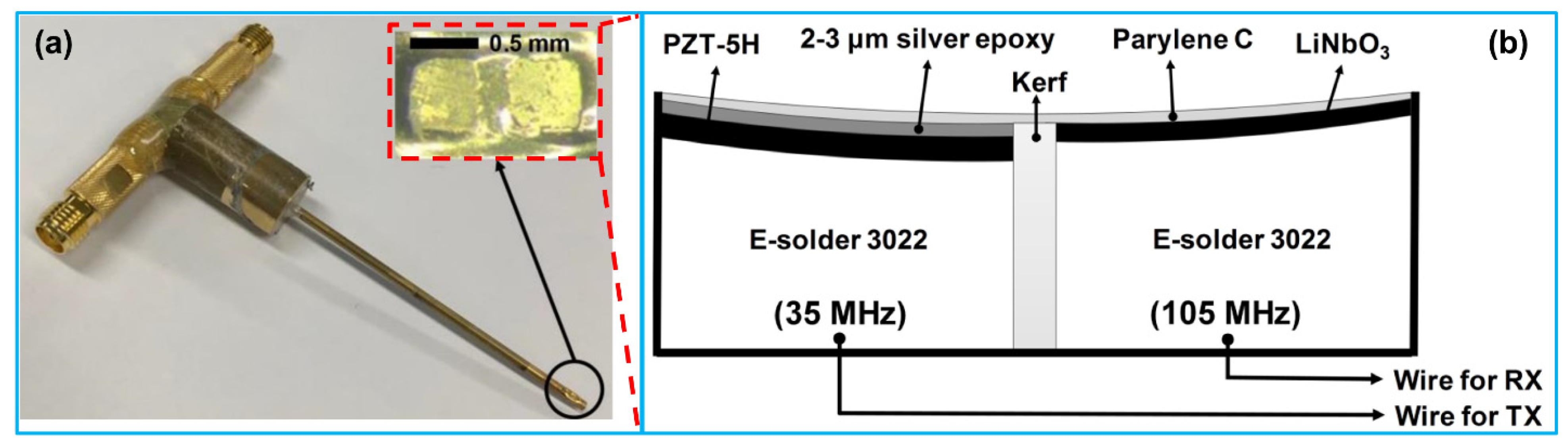
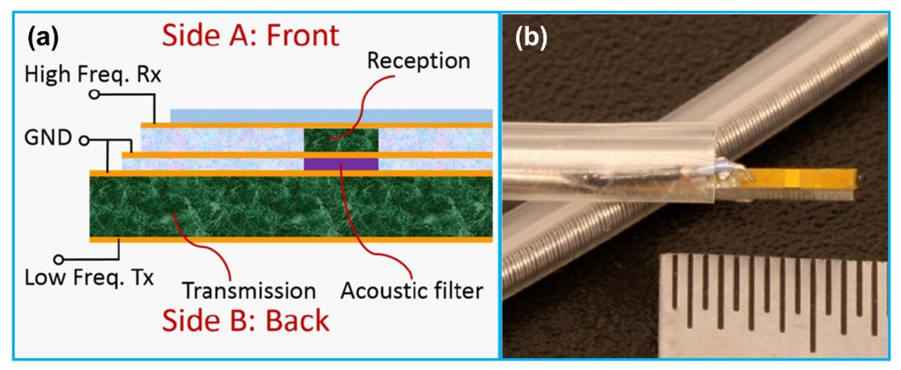
3.2. Dual Frequency IVUS Transducer

Even though various high frequency IVUS transducers have been reported with an enhanced axial resolution ranging 25–40 µm, their penetration depth is limited by the greater acoustic attenuation at higher frequencies. For the clinical applications, the desired IVUS imaging performance is a spatial resolution high enough to evaluate the thickness of fibrous cap (typically <65 µm) and a penetration depth >5 mm [110]. However, these two requirements cannot be met at the same time since the penetration depth is reduced due to the frequency-dependent acoustic attenuation while the transducer frequency is increased to achieve the desired spatial resolution. To overcome the inherent tradeoff between the acoustic attenuation and spatial resolution, a dual frequency transducer structure has been reported [74,111]. Two IVUS transducers with different frequencies are placed in catheter; the transducer with lower frequency (20–40 MHz) ensures large penetration depth while the other transducer with higher frequency (80–150 MHz) provides high resolution for superficial microstructure imaging. The configuration of these two transducers can be categorized into two types: side-by-side [112,113] and back-to-back [74,111]. In side-by-side configuration (Figure 6a), two IVUS transducers are arranged axially along the catheter with a center-to-center spacing of ~1–3 mm; the IVUS image co-registration is performed via pull-back scanning of the catheter. In back-to-back configuration (Figure 6b), two transducers are aligned bidirectionally in the thickness direction; the image co-registration is accomplished by rotating the catheter by 180°. A comparison of the reported dual frequency IVUS transducers for imaging is illustrated in Table 6.

3.3. Multifrequency IVUS Imaging

Tissue harmonic imaging, a widely used technique in commercial ultrasound systems to simultaneously improve the spatial and contrast resolutions of ultrasound images, has also been reported to enhance the spatial resolution of IVUS images while maintaining penetration depth. While ultrasound waves propagate into the human tissue, the harmonic components of the transmitted ultrasound waves are generated caused by the nonlinear nature of biological media [117]. It has been shown that the energy of harmonics is nonlinearly dependent on the transmitted acoustic pressure; in particular, the energy of second harmonic is proportional to the square of transmitted acoustic pressure [118]. It means that harmonics are mainly generated from the energy of the main lobe in the transmitted beam profile. Due to the low energy levels of the side and grating lobes in the harmonic beam profile, enhanced contrast resolution can be achieved [119,120]. Moreover, compared to the transmitted beam profile, the main lobe width of a harmonic beam profile is narrower; it reduces as the harmonic order increases [121]. Thus, compared with fundamental ultrasound imaging, tissue harmonic imaging can provide a higher spatial resolution; the resolution will also increase with the rise of harmonic order. Currently, the second harmonic imaging is adopted in most of ultrasound imaging systems [120], in which an ultrasound transducer is employed for both transmitting fundamental ultrasound waves and receiving second harmonic waves. For this end, an ultrasound transducer with a −6 dB bandwidth > 70% should be developed [115]. Even though using piezoelectric 1-3 composite for transducer fabrication can achieve a bandwidth > 70% at the expense of transmitting ultrasound pressure as a result of lowering mechanical quality factor [95,122], it is challenging to fabricate a miniature IVUS transducer with high frequency and desired structure [123,124]. Considering this perspective, dual frequency transducers with two different center frequencies will be the best choice for high frequency tissue harmonic imaging.
While the side-by-side configuration of dual frequency transducers is applicable for tissue harmonic imaging, the simple arrangement of two transducer elements cannot work well since the harmonic signals cannot receive effectively resulting from the different focal depths of the two elements. Recently, Lee et al. [110] developed a three-element, dual frequency IVUS transducer for tissue harmonic imaging. The three elements were arranged side by side in the horizontal direction and formed a spherical shape. Based on their phantom imaging results, the tissue harmonic imaging demonstrated higher spatial resolution and imaging contrast as well as lager imaging depth than that of the 70 MHz fundamental imaging. Following this work, Lee et al. [115] fabricated a dual-element, dual frequency IVUS transducer for harmonic imaging; one element with a center frequency of 35 MHz was used as transmitter, and the other element with a center frequency of 70 MHz was used for receiving the second harmonic signals. In addition, Lee et al. [114] developed a dual-element, dual frequency IVUS transducer for the third harmonic imaging as well (Figure 7). The two elements were also arranged side-by-side and spherically shaped with a radius of 2.5 mm. One element having a center frequency of 35 MHz was used for ultrasound transmission and the other element having a center frequency of 105 MHz was used for receiving the third harmonic signals. The phantom imaging results showed that the produced third harmonic images had higher spatial resolution and larger penetration depth than the fundamental images. The comparison of the spatial resolution of harmonic image with that of fundamental image are showed in Table 7.
Dual frequency IVUS transducers for superharmonic imaging with ultrasound contrast agents were also developed [125,126,127]. The two elements of the transducer were stacked vertically with co-aligned transmit and receive beams and electrically separated by a frequency selective isolation layer between them (Figure 8). The lower layer element having a low center frequency of 2–10 MHz transmitted acoustic waves to oscillate contrast agents; the upper layer element having a high center frequency of 10–30 MHz received superharmonic signals generated by the contrast agents. This kind of contrast enhanced IVUS imaging technique has been successfully applied for imaging vas vasorum, a microvasculature with a diameter < 200 µm that is closely related to early atherosclerotic plaque [128,129]. For example, Ma et al. [125,130] developed a dual frequency (6.5/30 MHz) IVUS transducer to excite microbubbles near their resonance and detect their superharmonic vibrations. The lower layer 6.5 MHz element had an aperture of 0.6 mm × 3 mm; the upper layer 30 MHz element had an aperture of 0.6 mm × 0.5 mm. The receiving element demonstrated a −6 dB bandwidth of ~60%, illustrating a broadband microbubble response. Based on the phantom imaging results, a high contrast-to-tissue ratio of 12 dB and axial resolution of 200 µm were achieved. Following that work, several other dual frequency IVUS transducers for microbubble contrast agent imaging have also been reported by the group [131,132,133]. Martin et al. [134] developed a dual frequency (5.5/37 MHz) IVUS transducer for visualizing contrast flow in micro-vessels. While the B-mode imaging showed a slightly higher contrast enhancement compared with the dual frequency mode, the dual frequency mode illustrated the capability of suppressing the tissue harmonics effectively with a lower tissue-to-noise ratio. The isolation layer or the acoustic filter between the transmitting and receiving element is a critical component to control wave propagation in multi-frequency system. An acoustic filter is mainly utilized to prevent the high-frequency wave from backward propagation while passing the forward low-frequency wave efficiently. Ma et al. [135] explored the acoustic filter design criteria according to the microwave transmission line theory. Based on their design, the acoustic filter layer was proved to suppress the high frequency aliasing echo by 14.5 dB and amplify the low frequency transmission by 8.0 dB, increasing an axial resolution from 416 µm to 86 µm in imaging. In addition, in order to optimize the dual frequency transducer design for the contrast enhanced IVUS imaging, Ma et al. [136] studied the impact of IVUS transducer layouts, transmitting frequencies and active materials on the imaging performance. They found that the stacked configuration showed the advantage over the other transducer configurations in the uniformity of the transmitting beam profile without a drop of pressure near the center of the transducer, where the receiving element had the highest sensitivity. In addition to the dual frequency IVUS transducer development, in order to obtain high quality IVUS contrast images, new signal processing method was proposed [137] and an integrated IVUS contrast imaging system was developed for in-vitro phantom imaging tests [138].

3.4. Array for IVUS Imaging

More recently, piezoelectric array transducer has also emerged for IVUS imaging applications. Compared with single element IVUS transducers, IVUS array transducers demonstrate unique features. Unlike the single element transducers for mechanical/rotational catheters, the solid-state catheter integrated with an IVUS array transducer can get rid of the non-uniform rotational displacements and the off-axis errors due to its stationary design. Furthermore, an IVUS array transducer can be adopted with beamforming during transmitting and receiving, which can increase the frame rates and decrease the point spread functions, thus optimizing the image quality.

3.4.1. Single Frequency Array

Cabrera-Munoz et al. [140] reported a 30 MHz forward-looking phased array transducer which was composed of 32-element of 2-2 PMN-PT composite for IVUS imaging. The array transducer had a dimension of 0.8 mm × 1 mm, and a natural focal depth of 5 mm. The phantom imaging results demonstrated that the array showed a −6 dB bandwidth of 36.4%, and axial and lateral resolutions of 65 µm and 215 µm, respectively. Based on the porcine carotid artery phantom imaging evaluation results, the array provided a penetration depth > 5 mm for IVUS imaging. Following this work, Cabrera-Munoz et al. [141] fabricated a 15 MHz side-looking phased array transducer as well, which was composed of 64-element of 2-2 PMN-PT composite. The fabricated array showed an aperture of 3.2 mm × 1.8 mm, which could be integrated into a 10 Fr catheter. The phantom imaging results demonstrated that the array illustrated axial and lateral resolutions of 90 µm and 420 µm, respectively, and an imaging penetration depth > 8 mm. In another work, Li et al. [142] developed a 40 MHz circular array with micromachined PMN-PT 1-3 composite elements for IVUS imaging (Figure 9a,b). The circular array consisted of 50 elements with a pitch of 100 µm around a needle, having an outer diameter of 1.7 mm. Using the deep reactive ion etching method, the PMN-PT 1-3 composite was fabricated with a pillar diameter of 18 µm and a kerf of 3 µm. The developed array demonstrated a center frequency of ~39 MHz and a −6 dB bandwidth of ~82%. In vitro phantom imaging results demonstrated that the circular array had an axial resolution of 60 µm with a penetration depth of 3 mm, and a dynamic range of 30 dB.

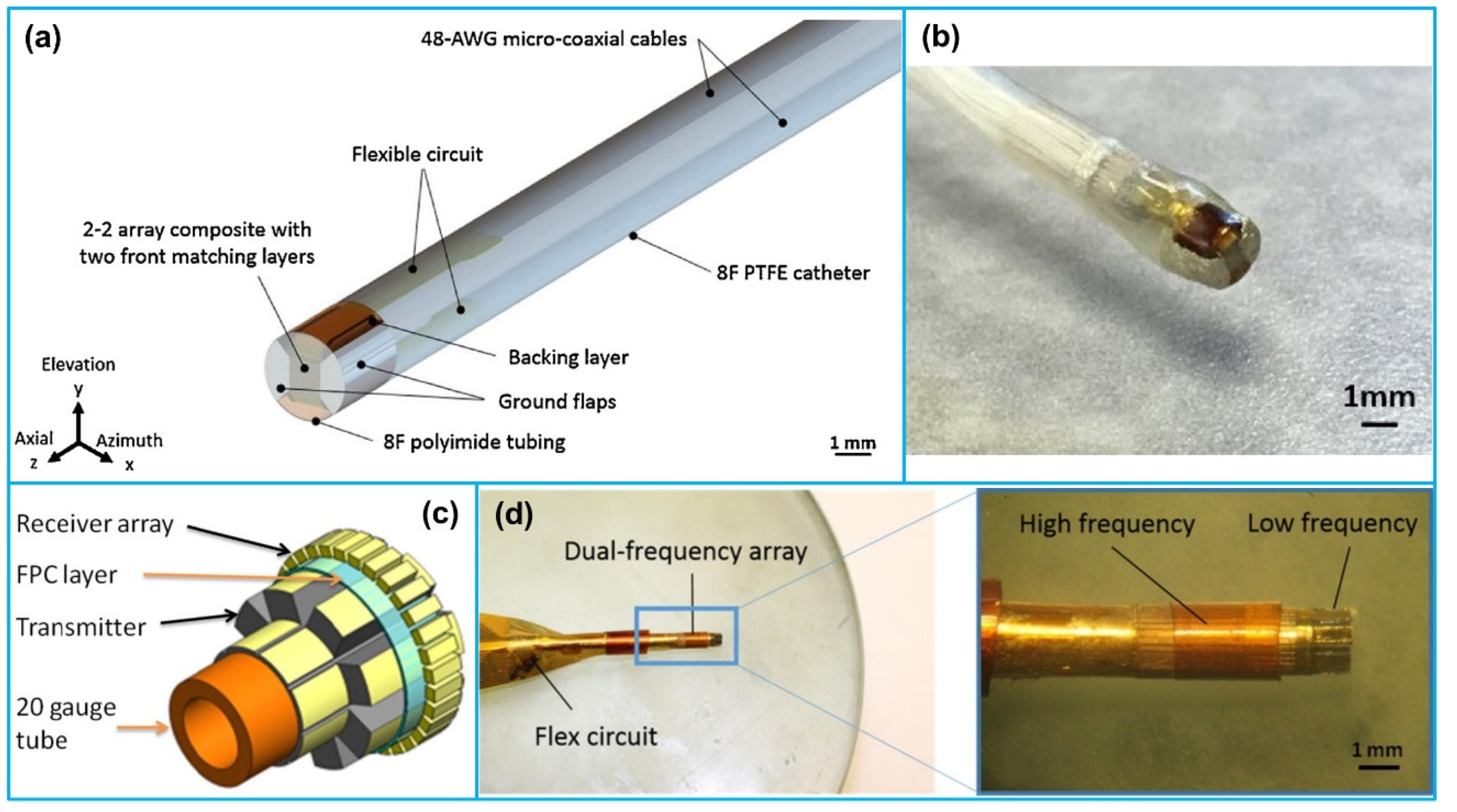
3.4.2. Dual Frequency Array

More recently, Wang et al. [143,144] reported a dual frequency IVUS cylindrical array with a reduced form-factor lateral mode transmitter (2.25 MHz) and a high frequency receiver (30 MHz) for contrast enhanced IVUS imaging (Figure 9c,d). The low-frequency transmitter contained 8 PMN-PT elements with a pitch size of 650 µm; the high-frequency receiver contained 32 PMN-PT elements with a pitch size of 160 µm. In vitro superharmonic imaging of a 200 µm tube showed that the axial resolution of the dual frequency array was 162 µm with a contrast-to-noise ratio of 16.6 dB. Wu et al. [145] fabricated a dual frequency (7/35 MHz) circular array for contrast enhanced IVUS imaging as well. The 7 MHz transmit array was composed of 8 PZT-5H 1-3 composite elements with a pitch of 200 µm and pillar dimension of 160 µm; the 35 MHz receive array consisted of 32 PMN-PT 1-3 composite elements with a kerf of 3 µm and pillar diameter of 18 µm. The dual frequency circular array was wrapped around a 1.2 mm-diameter needle for IVUS imaging. Their characterization results showed that the average −6 dB bandwidth of the receiving elements was ~68%, demonstrating a broad bandwidth for detecting microbubble response.

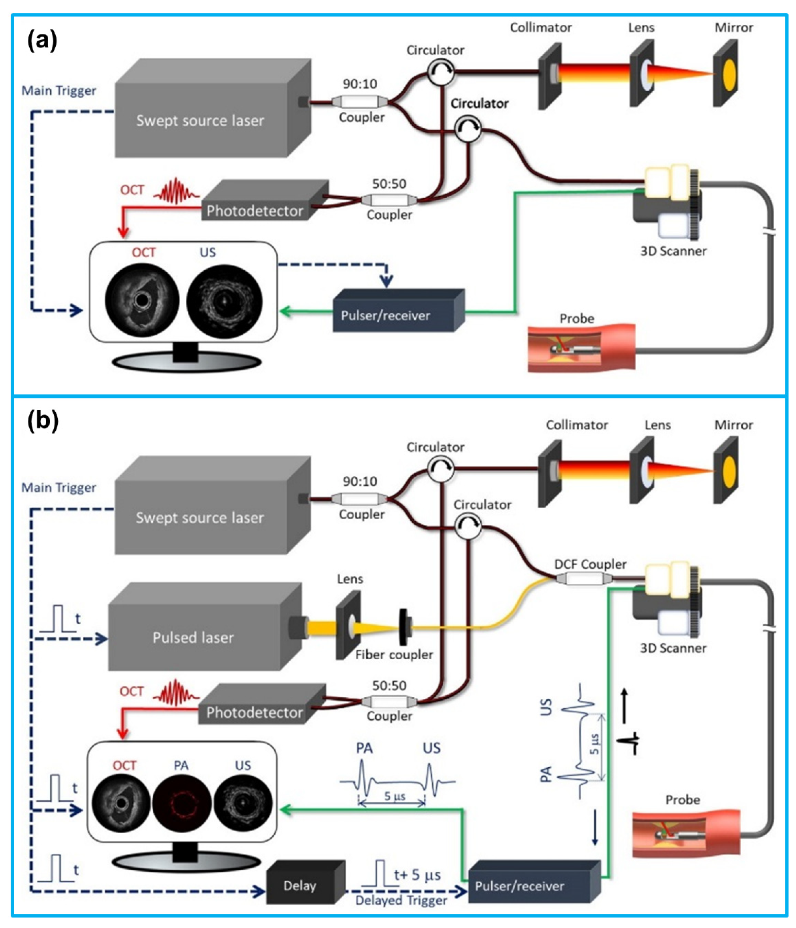
4. IVUS-Based Multimodality Intravascular Imaging

Even though IVUS imaging can provide the cross-sectional visualization of the coronary artery wall and the quantitative evaluation of the lumen size and plaque characteristics [146,147], its intrinsic limitations including the low spatial resolution and considerable noise hinder the detailed assessment of plaque composition and visualization of microfeatures of plaque that are associated with increased vulnerability [148,149,150]. In order to address these limitations and provide a complete assessment of coronary artery, over the past two decades, alternative intravascular imaging techniques, including optical coherence tomography (OCT) [151,152], near-infrared spectroscopic (NIRS) imaging [153,154], intravascular photoacoustic (IVPA) imaging [155,156], near infrared fluorescence (NIRF) imaging [157,158], time resolved fluorescence spectroscopic (TRFS) imaging [159,160] and fluorescence lifetime imaging (FLIM) [161,162], have been emerged as a result of the miniaturization of medical devices and advances in image processing. Since the working principles of these intravascular imaging modalities have been thoroughly reviewed elsewhere, this review will concentrate on their intravascular coronary imaging applications.
As the optical analogue of IVUS, OCT is an emerging imaging modality that uses low coherence light to perform cross-sectional imaging of the arterial wall with a high resolution of 1–15 µm [163]. Similar to IVUS, during intravascular imaging process, an OCT catheter with an imaging core at the distal end is firstly advanced into the region of interest. Blood needs to be removed from the region of interest by flushing with contrast or saline or using an occlusive method [164]. The catheter is then automatically pulled back with a speed of 1–25 mm/s as it images the vessel. Due to its superior resolution, the presence of neo-vessels and micro-calcifications, and the thickness of fibrous cap can be visualized [165]. However, the key limitation of OCT is its low penetration depth of 0.5–2 mm that is not sufficient to visualize the entire vessel wall and discriminate lipid from calcific tissue. Other limitation is that it requires temporal clearance of blood by using saline flushes or an occlusive balloon to overcome the blood interference problem [164].
NIRS, a spectroscopic technique that has been commonly used in industries for both qualitative and quantitative measurements of chemicals, has been commercialized for the study of coronary atherosclerosis and plaque composition [166,167]. Since different organic molecules absorb and scatter the near-infrared light at different degrees and wavelengths [168], the chemical composition of plaque can be obtained by analyzing the spectrum of the scattered light. Similar to IVUS and OCT imaging, a catheter is advanced into the artery of interest and cross-sectional images of the arterial segment are obtained via withdrawing the catheter. A color map is assigned to the image, known as chemogram, which indicates the probability of the presence of lipid-rich plaques in each region [169]. Even though NIRS imaging provides a reliable and quantitative assessment of lipid-core plaques, it cannot assess lumen size, vessel wall dimension and plaque burden. In addition, it cannot provide information about the depth of the lipid component into the vessel wall [21].
IVPA imaging that is based on localized thermal expansion, uses a nanosecond laser to excite biological tissues to generate acoustic waves [155,156]. The generated acoustic waves propagate through tissues and are received by an ultrasound transducer. The acoustic signal strength is proportional to the absorption coefficient of the tissue as well as the light intensity. Based on the tissue absorption coefficient which is related to the chemical composition of the tissue, IVPA image permits differentiation of the tissue types. The photoacoustic excitation wavelength can be selected to generate absorption contrast between the relevant components in the vessel wall and plaque, such as collagen, calcified tissue and lipids, allowing characterization of plaque composition [170,171,172]. While IVPA imaging provides high-detailed information about plaque chemical composition, it cannot provide any information about lumen size, vessel wall and plaque dimensions, as well as plaque distribution. Moreover, similar to optical intravascular imaging techniques, it requires blood clearance to get high quality image [173].
NIRF imaging is an emerging cellular and molecular imaging technique that uses laser induced NIR signal to stimulate NIRF emission of vessel wall and plaques that have injected with fluorescence-imaging agents [174]. It has been demonstrated that the activity of plaque inflammation can be detected by injecting an imaging contrast agent to the sites of the inflamed tissues [175]. The limitations of NIRF imaging are its inability to assess lumen size, vessel wall and plaque dimensions and compositions, as well as provide depth information. In addition, it requires injection of an activatable agent [176].
TRFS and FLIM are the extensions of fluorescence spectroscopy [177]. They are used to monitor the change in fluorescence over time (picoseconds to milliseconds) of a sample when irradiated with UV, visible or NIR light [178]. Since structural proteins and lipid constituents in atherosclerotic plaques have distinct fluorescence properties, changes in plaque composition can be evaluated through analysis of various fluorescence-derived parameters such as intensity, spectra or lifetime values [179]. Studies have reported that the application of these fluorescence techniques can assess plaques with TCFA and discriminate of lipid-rich and inflamed tissues [180]. The major limitations of TRFS and FLIM include their inability to assess lumen size, vessel wall morphology and dimension, as well as plaque burden. The comparison of different intravascular imaging techniques is summarized in Table 8.
While each intravascular imaging modality has unique features that supply critical information about the extent and severity of atherosclerosis, they also possess inherent limitations that prevent complete evaluation of the coronary arteries. To address this challenge, multi-modality intravascular imaging that combines different imaging techniques with complementary strengths into advanced images has been proposed and developed. Since the multimodal intravascular imaging technology has been reviewed extensively by many researchers [21,181,182,183,184], in this section, we concentrate on the reported applications of IVUS-based dual-modality intravascular imaging including IVUS-OCT, IVUS-NIRS, IVUS-IVPA, IVUS-NIRF, IVUS-TRFS (FLIM) and tri-modality intravascular imaging including IVUS-OCT-NIRF and IVUS-OCT-IVPA. Representative dual-modality and tri-modality intravascular imaging systems are demonstrated in Figure 10. The comparison of these multi-modality intravascular imaging techniques for evaluation of vulnerable plaques is illustrated in Table 9. Currently, both IVUS-OCT and IVUS-NIRS imaging catheter systems are commercially available. Other multi-modality intravascular imaging systems have been developed and tested ex vivo and pre-clinical in vivo settings. A summary of the reported multi-modality intravascular imaging catheters is shown in Table 10.

5. Conclusions and Perspectives

In this paper, the recent advances in ultrasound transducers for IVUS imaging were comprehensively reviewed. The basic IVUS imaging principle and the recently emerged IVUS image processing techniques were firstly presented. Three major evaluation parameters including spatial resolution, imaging sensitivity and image contrast for IVUS imaging were then summarized. Afterwards, two types of IVUS catheters including mechanical/rotational catheter and solid-state catheter were reviewed. Following that, three types of ultrasound transducers (piezoelectric ultrasound transducer, PMUT, CMUT) for IVUS imaging were examined in detail. In particular, the recent development of piezoelectric ultrasound transducers for IVUS imaging was extensively reviewed based on their working mechanisms, configurations and active materials adopted. Finally, the IVUS-based multimodality intravascular imaging was summarized and compared.
Even though IVUS imaging has become an established technique in clinical settings, its relatively low resolution made it difficult to accurately measure the fibrous cap thickness. In order to achieve both high resolution for detecting superficial plaque features and large penetration depth for visualizing overall morphology of vessel wall, high frequency ultrasound transducer based on PC-MUT technology has been developed, which illustrates the promise for clinical applications. Another area of active exploration is to develop dual frequency IVUS transducers. While it has been shown that the low frequency element could achieve an imaging capability similar to that of existing commercial catheters, and the high frequency element improved the axial resolution at the cost of reduced penetration depth, the feasibility of the dual frequency IVUS transducer needs to be further validated in a more clinically relevant catheter design. Moreover, while the in vitro phantom imaging results of both multifrequency IVUS imaging and array imaging were promising, in vivo imaging of atherosclerotic plaques has not been conducted with the developed transducers. Considering that each intravascular imaging modality has its own unique strengths and limitations, further integration of two or more imaging modalities to supplement each other’s weaknesses will advance the characterization of vulnerable plaques and aid in atherosclerosis diagnosis. In addition, further miniaturizing of the multimodality intravascular catheter will be favorable while delivering such catheter into the complex and confined coronary circulation system.

Author Contributions

Conceptualization, X.J., S.K. and X.D.; writing—original draft preparation, C.P. and H.W.; writing—review and editing, C.P., H.W., S.K., X.D. and X.J.; supervision, project administration and funding acquisition, X.J. All authors have read and agreed to the published version of the manuscript.

Funding

C.P., H.W. and X.J. would like to acknowledge the financial support from the National Institutes of Health under the grants R01HL141967 and R21EB027304.

Institutional Review Board Statement

Not applicable.

Informed Consent Statement

Not applicable.

Data Availability Statement

Not applicable.

Acknowledgments

We appreciate the anonymous reviewers for their careful reading of our manuscript and their many insightful comments and suggestions to help improve and clarify this manuscript.

Conflicts of Interest

Xiaoning Jiang has a financial interest in SonoVascular, Inc., who licensed an intravascular sonothrombolysis technology from North Carolina State University.

References

  1. World Health Organization (WHO). Cardiovascular Diseases (CVDs). Available online: https://www.who.int/news-room/fact-sheets/detail/cardiovascular-diseases-(cvds) (accessed on 6 January 2021).
  2. World Health Organization (WHO). About Cardiovascular Diseases. Available online: https://www.who.int/cardiovascular_diseases/about_cvd/en/ (accessed on 6 January 2021).
  3. Virmani, R.; Kolodgie, F.D.; Burke, A.P.; Farb, A.; Schwartz, S.M. Lessons from sudden coronary death: A comprehensive morphological classification scheme for atherosclerotic lesions. Arterioscler. Thromb. Vasc. Biol. 2000, 20, 1262–1275. [Google Scholar] [CrossRef] [PubMed] [Green Version]
  4. Libby, P.; Ridker, P.M.; Maseri, A. Inflammation and atherosclerosis. Circulation 2002, 105, 1135–1143. [Google Scholar] [CrossRef] [PubMed]
  5. Frostegård, J. Immunity, atherosclerosis and cardiovascular disease. BMC Med. 2013, 11, 1–13. [Google Scholar] [CrossRef] [PubMed] [Green Version]
  6. Shah, P.K. Mechanisms of plaque vulnerability and rupture. J. Am. Coll. Cardiol. 2003, 41, S15–S22. [Google Scholar] [CrossRef] [Green Version]
  7. Miller, J.D. Orbicular origins. Nat. Mater. 2013, 12, 476–478. [Google Scholar] [CrossRef] [PubMed]
  8. Venugopal, S.K.; Anoruo, M.; Jialal, I. Biochemistry, Low Density Lipoprotein; StatPearls Publishing LLC: Treasure Island, FL, USA, 2020. [Google Scholar]
  9. Falk, E.; Nakano, M.; Bentzon, J.F.; Finn, A.V.; Virmani, R. Update on acute coronary syndromes: The pathologists’ view. Eur. Heart J. 2013, 34, 719–728. [Google Scholar] [CrossRef] [Green Version]
  10. Libby, P.; Theroux, P. Pathophysiology of coronary artery disease. Circulation 2005, 111, 3481–3488. [Google Scholar] [CrossRef] [Green Version]
  11. Liang, M.; Puri, A.; Devlin, G. The vulnerable plaque: The real villain in acute coronary syndromes. Open Cardiovasc. Med. J. 2011, 5, 123. [Google Scholar] [CrossRef] [Green Version]
  12. Stefanadis, C.; Antoniou, C.; Tsiachris, D.; Pietri, P. Coronary atherosclerotic vulnerable plaque: Current perspectives. J. Am. Heart Assoc. 2017, 6, e005543. [Google Scholar] [CrossRef] [Green Version]
  13. Virmani, R.; Burke, A.P.; Kolodgie, F.D.; Farb, A. Pathology of the thin-cap fibroatheroma: A type of vulnerable plaque. J. Interv. Cardiol. 2003, 16, 267–272. [Google Scholar] [CrossRef]
  14. Thim, T.; Hagensen, M.K.; Bentzon, J.F.; Falk, E. From vulnerable plaque to atherothrombosis. J. Intern. Med. 2008, 263, 506–516. [Google Scholar] [CrossRef] [PubMed]
  15. Virmani, R.; Burke, A.P.; Farb, A.; Kolodgie, F.D. Pathology of the vulnerable plaque. J. Am. Coll. Cardiol. 2006, 47, C13–C18. [Google Scholar] [CrossRef] [PubMed] [Green Version]
  16. Sakakura, K.; Nakano, M.; Otsuka, F.; Ladich, E.; Kolodgie, F.D.; Virmani, R. Pathophysiology of atherosclerosis plaque progression. Heart Lung Circ. 2013, 22, 399–411. [Google Scholar] [CrossRef] [PubMed] [Green Version]
  17. Tarkin, J.M.; Dweck, M.R.; Evans, N.R.; Takx, R.A.P.; Brown, A.J.; Tawakol, A.; Fayad, Z.A.; Rudd, J.H.F. Imaging atherosclerosis. Circ. Res. 2016, 118, 750–769. [Google Scholar] [CrossRef] [Green Version]
  18. Weinreich, M.; Litwok, Y.; Mui, L.W.; Lau, J.F. Advanced vascular imaging. Vasc. Med. 2017, 22, 73–76. [Google Scholar] [CrossRef]
  19. Mantella, L.E.; Liblik, K.; Johri, A.M. Vascular imaging of atherosclerosis: Strengths and weaknesses. Atherosclerosis 2021, 319, 42–50. [Google Scholar] [CrossRef]
  20. Joshi, F.R.; Lindsay, A.C.; Obaid, D.R.; Falk, E.; Rudd, J.H.F. Non-invasive imaging of atherosclerosis. Eur. Heart J. Cardiovasc. Imaging 2012, 13, 205–218. [Google Scholar] [CrossRef] [Green Version]
  21. Mushenkova, N.V.; Summerhill, V.I.; Zhang, D.; Romanenko, E.B.; Grechko, A.V.; Orekhov, A.N. Current Advances in the Diagnostic Imaging of Atherosclerosis: Insights into the Pathophysiology of Vulnerable Plaque. Int. J. Mol. Sci. 2020, 21, 2992. [Google Scholar] [CrossRef] [Green Version]
  22. Garcìa-Garcìa, H.M.; Gogas, B.D.; Serruys, P.W.; Bruining, N. IVUS-based imaging modalities for tissue characterization: Similarities and differences. Int. J. Cardiovasc. Imaging 2011, 27, 215–224. [Google Scholar] [CrossRef] [PubMed] [Green Version]
  23. Erglis, A.; Jegere, S.; Narbute, I. Intravascular ultrasound-based imaging modalities for tissue characterisation. Interv. Cardiol. Rev. 2014, 9, 151. [Google Scholar] [CrossRef] [PubMed]
  24. Koganti, S.; Kotecha, T.; Rakhit, R.D. Choice of intracoronary imaging: When to use intravascular ultrasound or optical coherence tomography. Interv. Cardiol. Rev. 2016, 11, 11. [Google Scholar] [CrossRef] [Green Version]
  25. Shammas, N.W.; Radaideh, Q.; Shammas, W.J.; Daher, G.E.; Rachwan, R.J.; Radaideh, Y. The role of precise imaging with intravascular ultrasound in coronary and peripheral interventions. Vasc. Health Risk Manag. 2019, 15, 283. [Google Scholar] [CrossRef] [PubMed] [Green Version]
  26. World Health Organization. Training in Diagnostic Ultrasound: Essentials, Principles and Standards: Report of a WHO Study Group; World Health Organization: Geneva, Switzerland, 1998; ISBN 9241208759. [Google Scholar]
  27. Shlofmitz, E.; Zhu, B.; Khalid, N. Intravascular Ultrasound (IVUS); StatPearls Publishing LLC: Treasure Island, FL, USA, 2021. [Google Scholar]
  28. Libby, P.; Buring, J.E.; Badimon, L.; Hansson, G.K.; Deanfield, J.; Bittencourt, M.S.; Tokgözoğlu, L.; Lewis, E.F. Atherosclerosis. Nat. Rev. Dis. Prim. 2019, 5, 56. [Google Scholar] [CrossRef]
  29. Schoenhagen, P.; Nissen, S.E. An Atlas and Manual of Coronary Intravascular Ultrasound Imaging; CRC Press: Boca Raton, FL, USA, 2003; ISBN 1135399433. [Google Scholar]
  30. Schoenhagen, P.; Nissen, S. Understanding coronary artery disease: Tomographic imaging with intravascular ultrasound. Heart 2002, 88, 91–96. [Google Scholar] [CrossRef] [PubMed] [Green Version]
  31. Jakabčin, J.; Špaček, R.; Bystroň, M.; Kvašňák, M.; Jager, J.; Veselka, J.; Kala, P.; Červinka, P. Long-term health outcome and mortality evaluation after invasive coronary treatment using drug eluting stents with or without the IVUS guidance. Randomized control trial. HOME DES IVUS. Catheter. Cardiovasc. Interv. 2010, 75, 578–583. [Google Scholar] [CrossRef] [PubMed]
  32. Papaioannou, T.G.; Kalantzis, C.; Katsianos, E.; Sanoudou, D.; Vavuranakis, M.; Tousoulis, D. Personalized assessment of the coronary atherosclerotic arteries by intravascular ultrasound imaging: Hunting the vulnerable plaque. J. Pers. Med. 2019, 9, 8. [Google Scholar] [CrossRef] [Green Version]
  33. Li, J.; Ma, T.; Mohar, D.; Steward, E.; Yu, M.; Piao, Z.; He, Y.; Shung, K.K.; Zhou, Q.; Patel, P.M. Ultrafast optical-ultrasonic system and miniaturized catheter for imaging and characterizing atherosclerotic plaques in vivo. Sci. Rep. 2015, 5, 1–7. [Google Scholar] [CrossRef] [PubMed]
  34. Murray, S.W.; Stables, R.H.; Palmer, N.D. Virtual histology imaging in acute coronary syndromes: Useful or just a research tool? J. Invasive Cardiol. 2010, 22, 84–91. [Google Scholar]
  35. Gao, J.; Wang, Y.-Y.; Liu, Y. Application of virtual histological intravascular ultrasound in plaque composition assessment of saphenous vein graft diseases. Chin. Med. J. 2019, 132, 957. [Google Scholar] [CrossRef]
  36. Nair, A.; Kuban, B.D.; Tuzcu, E.M.; Schoenhagen, P.; Nissen, S.E.; Vince, D.G. Coronary plaque classification with intravascular ultrasound radiofrequency data analysis. Circulation 2002, 106, 2200–2206. [Google Scholar] [CrossRef] [Green Version]
  37. Ng, A.; Swanevelder, J. Resolution in ultrasound imaging. Contin. Educ. Anaesth. Crit. Care Pain 2011, 11, 186–192. [Google Scholar] [CrossRef]
  38. Foster, F.S.; Pavlin, C.J.; Harasiewicz, K.A.; Christopher, D.A.; Turnbull, D.H. Advances in ultrasound biomicroscopy. Ultrasound Med. Biol. 2000, 26, 1–27. [Google Scholar] [CrossRef]
  39. Mintz, G.S.; Nissen, S.E.; Anderson, W.D.; Bailey, S.R.; Erbel, R.; Fitzgerald, P.J.; Pinto, F.J.; Rosenfield, K.; Siegel, R.J.; Tuzcu, E.M. American College of Cardiology clinical expert consensus document on standards for acquisition, measurement and reporting of intravascular ultrasound studies (ivus) A report of the american college of cardiology task force on clinical expert consensus doc. J. Am. Coll. Cardiol. 2001, 37, 1478–1492. [Google Scholar] [CrossRef] [Green Version]
  40. Gougheri, H.S.; Dangi, A.; Kothapalli, S.-R.; Kiani, M. A comprehensive study of ultrasound transducer characteristics in microscopic ultrasound neuromodulation. IEEE Trans. Biomed. Circuits Syst. 2019, 13, 835–847. [Google Scholar] [CrossRef] [PubMed]
  41. Üstüner, K.F.; Holley, G.L. Ultrasound imaging system performance assessment. In Proceedings of the AAPM Annual Meeting, San Diego, CA, USA, 10–14 August 2003. [Google Scholar]
  42. Agarwal, A.; Schneider, F.K.; Yoo, Y.M.; Kim, Y. Image quality evaluation with a new phase rotation beamformer. IEEE Trans. Ultrason. Ferroelectr. Freq. Control 2008, 55, 1947–1955. [Google Scholar] [CrossRef]
  43. Frimerman, A.; Abergel, E.; Blondheim, D.S.; Shotan, A.; Meisel, S.; Shochat, M.; Punjabi, P.; Roguin, A. Novel Method for Real Time Co-Registration of IVUS and Coronary Angiography. J. Interv. Cardiol. 2016, 29, 225–231. [Google Scholar] [CrossRef] [PubMed] [Green Version]
  44. Stigall, J.; Robinson, G. Flushing for Imaging Catheters. U.S. Patent Application No. 14/211,717, 2014. [Google Scholar]
  45. Balocco, S. Intravascular Ultrasound: From Acquisition to Advanced Quantitative Analysis; Elsevier: Amsterdam, The Netherlands, 2020; ISBN 0128188340. [Google Scholar]
  46. Nissen, S.E.; Yock, P. Intravascular ultrasound: Novel pathophysiological insights and current clinical applications. Circulation 2001, 103, 604–616. [Google Scholar] [CrossRef]
  47. Katouzian, A.; Angelini, E.D.; Carlier, S.G.; Suri, J.S.; Navab, N.; Laine, A.F. A state-of-the-art review on segmentation algorithms in intravascular ultrasound (IVUS) images. IEEE Trans. Inf. Technol. Biomed. 2012, 16, 823–834. [Google Scholar] [CrossRef] [Green Version]
  48. McDaniel, M.C.; Eshtehardi, P.; Sawaya, F.J.; Douglas, J.S.; Samady, H. Contemporary clinical applications of coronary intravascular ultrasound. JACC Cardiovasc. Interv. 2011, 4, 1155–1167. [Google Scholar] [CrossRef] [Green Version]
  49. Kitahara, H.; Honda, Y.; Fitzgerald, P.J. Intravascular Ultrasound BT—PanVascular Medicine; Lanzer, P., Ed.; Springer: Berlin/Heidelberg, Germany, 2015; pp. 1379–1418. ISBN 978-3-642-37078-6. [Google Scholar]
  50. Kwon, T.-G.; Cho, Y.J.; Bae, J.-H. Physical principles and equipment: IVUS. In Coronary Imaging and Physiology; Springer: Berlin/Heidelberg, Germany, 2018; pp. 3–7. [Google Scholar]
  51. Bangalore, S.; Bhatt, D.L. Coronary intravascular ultrasound. Circulation 2013, 127, e868–e874. [Google Scholar] [CrossRef] [Green Version]
  52. Jiang, X.; Yuan, J.R.; Cheng, A.; Snook, K.; Rehrig, P.W.; Shrout, T.R.; Hackenberger, W.S.; Cao, P.; Lavalelle, G.; Geng, X. 5I-1 Microfabrication of piezoelectric composite ultrasound transducers (PC-MUT). In Proceedings of the 2006 IEEE Ultrasonics Symposium, Vancouver, BC, Canada, 3–6 October 2006; 2006; pp. 922–925. [Google Scholar]
  53. Jung, J.; Lee, W.; Kang, W.; Shin, E.; Ryu, J.; Choi, H. Review of piezoelectric micromachined ultrasonic transducers and their applications. J. Micromech. Microeng. 2017, 27, 113001. [Google Scholar] [CrossRef]
  54. Wang, J.; Zheng, Z.; Chan, J.; Yeow, J.T.W. Capacitive micromachined ultrasound transducers for intravascular ultrasound imaging. Microsyst. Nanoeng. 2020, 6, 1–13. [Google Scholar] [CrossRef]
  55. Qiu, Y.; Gigliotti, J.V.; Wallace, M.; Griggio, F.; Demore, C.E.M.; Cochran, S.; Trolier-McKinstry, S. Piezoelectric micromachined ultrasound transducer (PMUT) arrays for integrated sensing, actuation and imaging. Sensors 2015, 15, 8020–8041. [Google Scholar] [CrossRef] [PubMed] [Green Version]
  56. Erguri, A.S.; Huang, Y.; Zhuang, X.; Oralkan, O.; Yarahoglu, G.G.; Khuri-Yakub, B.T. Capacitive micromachined ultrasonic transducers: Fabrication technology. IEEE Trans. Ultrason. Ferroelectr. Freq. Control 2005, 52, 2242–2258. [Google Scholar] [CrossRef] [PubMed]
  57. Salim, M.S.; Abd Malek, M.F.; Heng, R.B.W.; Juni, K.M.; Sabri, N. Capacitive micromachined ultrasonic transducers: Technology and application. J. Med. Ultrasound 2012, 20, 8–31. [Google Scholar] [CrossRef] [Green Version]
  58. Maeder, M.D.; Damjanovic, D.; Setter, N. Lead free piezoelectric materials. J. Electroceram. 2004, 13, 385–392. [Google Scholar] [CrossRef]
  59. Chorsi, M.T.; Curry, E.J.; Chorsi, H.T.; Das, R.; Baroody, J.; Purohit, P.K.; Ilies, H.; Nguyen, T.D. Piezoelectric biomaterials for sensors and actuators. Adv. Mater. 2019, 31, 1802084. [Google Scholar] [CrossRef] [PubMed] [Green Version]
  60. Trolier-McKinstry, S.; Muralt, P. Thin film piezoelectrics for MEMS. J. Electroceram. 2004, 12, 7–17. [Google Scholar] [CrossRef]
  61. Zhou, Q.; Lau, S.; Wu, D.; Shung, K.K. Piezoelectric films for high frequency ultrasonic transducers in biomedical applications. Prog. Mater. Sci. 2011, 56, 139–174. [Google Scholar] [CrossRef] [Green Version]
  62. Dausch, D.E.; Gilchrist, K.H.; Carlson, J.B.; Hall, S.D.; Castellucci, J.B.; von Ramm, O.T. In vivo real-time 3-D intracardiac echo using PMUT arrays. IEEE Trans. Ultrason. Ferroelectr. Freq. Control 2014, 61, 1754–1764. [Google Scholar] [CrossRef]
  63. Eccardt, P.C.; Niederer, K. Micromachined ultrasound transducers with improved coupling factors from a CMOS compatible process. Ultrasonics 2000, 38, 774–780. [Google Scholar] [CrossRef]
  64. Oralkan, O.; Ergun, A.S.; Johnson, J.A.; Karaman, M.; Demirci, U.; Kaviani, K.; Lee, T.H.; Khuri-Yakub, B.T. Capacitive micromachined ultrasonic transducers: Next-generation arrays for acoustic imaging? IEEE Trans. Ultrason. Ferroelectr. Freq. Control 2002, 49, 1596–1610. [Google Scholar] [CrossRef]
  65. Zhuang, X.; Lin, D.-S.; Oralkan, Ö.; Khuri-Yakub, B.T. Fabrication of flexible transducer arrays with through-wafer electrical interconnects based on trench refilling with PDMS. J. Microelectromech. Syst. 2008, 17, 446–452. [Google Scholar] [CrossRef]
  66. Xu, T.; Tekes, C.; Satir, S.; Arkan, E.; Ghovanloo, M.; Degertekin, F.L. Design, modeling and characterization of a 35MHz 1-D CMUT phased array. In Proceedings of the 2013 IEEE International Ultrasonics Symposium (IUS), Prague, Czech Republic, 21–25 July 2013; 2013; pp. 1987–1990. [Google Scholar]
  67. Lim, J.; Tekes, C.; Degertekin, F.L.; Ghovanloo, M. Towards a reduced-wire interface for CMUT-based intravascular ultrasound imaging systems. IEEE Trans. Biomed. Circuits Syst. 2016, 11, 400–410. [Google Scholar] [CrossRef]
  68. Pekař, M.; Mihajlović, N.; Belt, H.; Kolen, A.F.; Van Rens, J.; Budzelaar, F.; Jacobs, B.; Bosch, J.G.; Vos, H.J.; Rem-Bronneberg, D. Quantitative imaging performance of frequency-tunable capacitive micromachined ultrasonic transducer array designed for intracardiac application: Phantom study. Ultrasonics 2018, 84, 421–429. [Google Scholar] [CrossRef] [PubMed]
  69. Degertekin, F.L.; Guldiken, R.O.; Karaman, M. Annular-ring CMUT arrays for forward-looking IVUS: Transducer characterization and imaging. IEEE Trans. Ultrason. Ferroelectr. Freq. Control 2006, 53, 474–482. [Google Scholar] [CrossRef] [PubMed]
  70. Yeh, D.T.; Oralkan, O.; Wygant, I.O.; O’Donnell, M.; Khuri-Yakub, B.T. 3-D ultrasound imaging using a forward-looking CMUT ring array for intravascular/intracardiac applications. IEEE Trans. Ultrason. Ferroelectr. Freq. Control 2006, 53, 1202–1211. [Google Scholar] [CrossRef] [PubMed] [Green Version]
  71. Zahorian, J.; Hochman, M.; Xu, T.; Satir, S.; Gurun, G.; Karaman, M.; Degertekin, F.L. Monolithic CMUT-on-CMOS integration for intravascular ultrasound applications. IEEE Trans. Ultrason. Ferroelectr. Freq. Control 2011, 58, 2659–2667. [Google Scholar] [CrossRef] [PubMed] [Green Version]
  72. Gurun, G.; Tekes, C.; Zahorian, J.; Xu, T.; Satir, S.; Karaman, M.; Hasler, J.; Degertekin, F.L. Single-chip CMUT-on-CMOS front-end system for real-time volumetric IVUS and ICE imaging. IEEE Trans. Ultrason. Ferroelectr. Freq. Control 2014, 61, 239–250. [Google Scholar] [CrossRef] [PubMed] [Green Version]
  73. Manwar, R.; Simpson, T.; Bakhtazad, A.; Chowdhury, S. Fabrication and characterization of a high frequency and high coupling coefficient CMUT array. Microsyst. Technol. 2017, 23, 4965–4977. [Google Scholar] [CrossRef]
  74. Ma, T.; Yu, M.; Li, J.; Munding, C.E.; Chen, Z.; Fei, C.; Shung, K.K.; Zhou, Q. Erratum: Multi-frequency intravascular ultrasound (IVUS) imaging. IEEE Trans. Ultrason. Ferroelectr. Freq. Control 2015, 62, 604. [Google Scholar] [CrossRef] [PubMed]
  75. Qiu, W.; Wang, X.; Chen, Y.; Fu, Q.; Su, M.; Zhang, L.; Xia, J.; Dai, J.; Zhang, Y.; Zheng, H. Modulated excitation imaging system for intravascular ultrasound. IEEE Trans. Biomed. Eng. 2016, 64, 1935–1942. [Google Scholar] [CrossRef] [PubMed]
  76. MacNeill, B.D.; Lowe, H.C.; Takano, M.; Fuster, V.; Jang, I.-K. Intravascular modalities for detection of vulnerable plaque: Current status. Arterioscler. Thromb. Vasc. Biol. 2003, 23, 1333–1342. [Google Scholar] [CrossRef] [PubMed] [Green Version]
  77. van der Wal, A.C.; Becker, A.E. Atherosclerotic plaque rupture–pathologic basis of plaque stability and instability. Cardiovasc. Res. 1999, 41, 334–344. [Google Scholar] [CrossRef]
  78. Li, X.; Wu, W.; Chung, Y.; Shih, W.Y.; Shih, W.-H.; Zhou, Q.; Shung, K.K. 80-MHz intravascular ultrasound transducer using PMN-PT free-standing film. IEEE Trans. Ultrason. Ferroelectr. Freq. Control 2011, 58, 2281–2288. [Google Scholar]
  79. Sung, J.H.; Jeong, J.S. Development of high-frequency (>60 MHz) intravascular ultrasound (IVUS) transducer by using asymmetric electrodes for improved beam profile. Sensors 2018, 18, 4414. [Google Scholar] [CrossRef] [Green Version]
  80. Ma, X.; Cao, W. Single-Crystal High-Frequency Intravascular Ultrasound Transducer With 40-µm Axial Resolution. IEEE Trans. Ultrason. Ferroelectr. Freq. Control 2019, 67, 810–816. [Google Scholar] [CrossRef]
  81. Zhang, Q.; Pang, X.; Zhang, Z.; Su, M.; Hong, J.; Zheng, H.; Qiu, W.; Lam, K.H. Miniature transducer using PNN-PZT-based ceramic for intravascular ultrasound. IEEE Trans. Ultrason. Ferroelectr. Freq. Control 2019, 66, 1102–1109. [Google Scholar] [CrossRef]
  82. Fei, C.; Yang, Y.; Guo, F.; Lin, P.; Chen, Q.; Zhou, Q.; Sun, L. PMN-PT single crystal ultrasonic transducer with half-concave geometric design for IVUS imaging. IEEE Trans. Biomed. Eng. 2017, 65, 2087–2092. [Google Scholar] [CrossRef]
  83. Yoon, S.; Williams, J.; Kang, B.J.; Yoon, C.; Cabrera-Munoz, N.; Jeong, J.S.; Lee, S.G.; Shung, K.K.; Kim, H.H. Angled-focused 45 MHz PMN-PT single element transducer for intravascular ultrasound imaging. Sensors Actuators A Phys. 2015, 228, 16–22. [Google Scholar] [CrossRef] [Green Version]
  84. Lee, J.; Jang, J.; Chang, J.H. Oblong-shaped-focused transducers for intravascular ultrasound imaging. IEEE Trans. Biomed. Eng. 2016, 64, 671–680. [Google Scholar] [CrossRef] [PubMed]
  85. Panda, P.K. Environmental friendly lead-free piezoelectric materials. J. Mater. Sci. 2009, 44, 5049–5062. [Google Scholar] [CrossRef] [Green Version]
  86. Safari, A.; Abazari, M. Lead-free piezoelectric ceramics and thin films. IEEE Trans. Ultrason. Ferroelectr. Freq. Control 2010, 57, 2165–2176. [Google Scholar] [CrossRef] [PubMed]
  87. Yan, X.; Lam, K.H.; Li, X.; Chen, R.; Ren, W.; Ren, X.; Zhou, Q.; Shung, K.K. Correspondence: Lead-free intravascular ultrasound transducer using BZT-50BCT ceramics. IEEE Trans. Ultrason. Ferroelectr. Freq. Control 2013, 60, 1272–1276. [Google Scholar] [CrossRef] [PubMed] [Green Version]
  88. Zhu, B.; Zhang, Z.; Ma, T.; Yang, X.; Li, Y.; Shung, K.K.; Zhou, Q. (100)-Textured KNN-based thick film with enhanced piezoelectric property for intravascular ultrasound imaging. Appl. Phys. Lett. 2015, 106, 173504. [Google Scholar] [CrossRef] [PubMed] [Green Version]
  89. Fei, C.; Chiu, C.T.; Chen, X.; Chen, Z.; Ma, J.; Zhu, B.; Shung, K.K.; Zhou, Q. Ultrahigh frequency (100 MHz–300 MHz) ultrasonic transducers for optical resolution medical imagining. Sci. Rep. 2016, 6, 1–8. [Google Scholar] [CrossRef] [PubMed] [Green Version]
  90. Jiang, X.; Li, S.; Kim, J.; Ma, J. High Frequency Piezo-Composite Micromachined Ultrasound Transducer Array Technology for Biomedical Imaging; American Society of Mechanical Engineers: New York, NY, USA, 2017; ISBN 0791861635. [Google Scholar]
  91. Yin, J.; Lee, M.; Cherin, E.; Lukacs, M.; Foster, F.S. High frequency piezo-composite transducer with hexagonal pillars. In Proceedings of the 2009 IEEE International Ultrasonics Symposium, Rome, Italy, 20–23 September 2009; IEEE: Piscataway, NJ, USA, 2009; pp. 2750–2753. [Google Scholar]
  92. Brown, J.A.; Cherin, E.; Yin, J.; Foster, F.S. Fabrication and performance of high-frequency composite transducers with triangular-pillar geometry. IEEE Trans. Ultrason. Ferroelectr. Freq. Control 2009, 56, 827–836. [Google Scholar] [CrossRef]
  93. Yuan, J.R.; Jiang, X.; Cao, P.-J.; Sadaka, A.; Bautista, R.; Snook, K.; Rehrig, P.W. 5C-5 high frequency piezo composites microfabricated ultrasound transducers for intravascular imaging. In Proceedings of the 2006 IEEE Ultrasonics Symposium, Vancouver, BC, Canada, 3–6 October 2006; IEEE: Piscataway, NJ, USA, 2006; pp. 264–268. [Google Scholar]
  94. Yuan, J.; Rhee, S.; Jiang, X.N. 60 MHz PMN-PT based 1-3 composite transducer for IVUS imaging. In Proceedings of the 2008 IEEE Ultrasonics Symposiumn, Beijing, China, 2–5 November 2008; IEEE: Piscataway, NJ, USA, 2008; pp. 682–685. [Google Scholar]
  95. Jiang, X.; Snook, K.; Cheng, A.; Hackenberger, W.S.; Geng, X. Micromachined PMN-PT single crystal composite transducers--15–75 MHz PC-MUT. In Proceedings of the 2008 IEEE Ultrasonics Symposiumn, Beijing, China, 2–5 November 2008; IEEE: Piscataway, NJ, USA, 2008; pp. 164–167. [Google Scholar]
  96. Li, X.; Ma, T.; Tian, J.; Han, P.; Zhou, Q.; Shung, K.K. Micromachined PIN-PMN-PT crystal composite transducer for high-frequency intravascular ultrasound (IVUS) imaging. IEEE Trans. Ultrason. Ferroelectr. Freq. Control 2014, 61, 1171–1178. [Google Scholar] [CrossRef] [PubMed]
  97. Chen, R.; Wu, J.; Lam, K.H.; Yao, L.; Zhou, Q.; Tian, J.; Han, P.; Shung, K.K. Thermal-independent properties of PIN-PMN-PT single-crystal linear-array ultrasonic transducers. IEEE Trans. Ultrason. Ferroelectr. Freq. Control 2012, 59, 2777–2784. [Google Scholar]
  98. Zhang, S.; Li, F.; Jiang, X.; Kim, J.; Luo, J.; Geng, X. Advantages and challenges of relaxor-PbTiO3 ferroelectric crystals for electroacoustic transducers–A review. Prog. Mater. Sci. 2015, 68, 1–66. [Google Scholar] [CrossRef] [Green Version]
  99. Zhang, S.; Li, F.; Yu, F.; Jiang, X.; Lee, H.-Y.; Luo, J.; Shrout, T.R. Recent developments in piezoelectric crystals. J. Korean Ceram. Soc. 2018, 55, 419–439. [Google Scholar] [CrossRef] [Green Version]
  100. Li, Z.; Lv, J.; Zhu, X.; Cui, Y.; Jian, X. Development of High Frequency Piezocomposite with Hexagonal Pillars via Cold Ablation Process. Ultrasonics 2021, 114, 106404. [Google Scholar] [CrossRef]
  101. Xu, J.; Han, Z.; Wang, N.; Li, Z.; Lv, J.; Zhu, X.; Cui, Y.; Jian, X. Micromachined High Frequency 1-3 Piezocomposite Transducer using Picosecond Laser. IEEE Trans. Ultrason. Ferroelectr. Freq. Control 2021. [Google Scholar] [CrossRef] [PubMed]
  102. Uribe-Patarroyo, N.; Bouma, B.E. Rotational distortion correction in endoscopic optical coherence tomography based on speckle decorrelation. Opt. Lett. 2015, 40, 5518–5521. [Google Scholar] [CrossRef] [PubMed] [Green Version]
  103. Peng, J.; Ma, L.; Li, X.; Tang, H.; Li, Y.; Chen, S. A novel synchronous micro motor for intravascular ultrasound imaging. IEEE Trans. Biomed. Eng. 2018, 66, 802–809. [Google Scholar] [CrossRef] [PubMed]
  104. Cagatay, S.; Koc, B.; Uchino, K. A 1.6-mm, metal tube ultrasonic motor. IEEE Trans. Ultrason. Ferroelectr. Freq. Control 2003, 50, 782–786. [Google Scholar] [CrossRef]
  105. Zhang, H.; Dong, S.; Zhang, S.; Wang, T.; Zhang, Z.; Fan, L. Ultrasonic micro-motor using miniature piezoelectric tube with diameter of 1.0 mm. Ultrasonics 2006, 44, e603–e606. [Google Scholar] [CrossRef]
  106. Tanabe, M.; Xie, S.; Tagawa, N.; Moriya, T.; Furukawa, Y. Development of a mechanical scanning-type intravascular ultrasound system using a miniature ultrasound motor. Jpn. J. Appl. Phys. 2007, 46, 4805. [Google Scholar] [CrossRef]
  107. Watson, B.; Friend, J.; Yeo, L. Piezoelectric ultrasonic micro/milli-scale actuators. Sensors Actuators A Phys. 2009, 152, 219–233. [Google Scholar] [CrossRef]
  108. Mashimo, T. Performance evaluation of a micro ultrasonic motor using a one-cubic-millimeter stator. IEEE Trans. Ultrason. Ferroelectr. Freq. Control 2015, 62, 1819–1826. [Google Scholar] [CrossRef] [PubMed]
  109. Zhang, J.; Lu, S.; Liao, X.; Feng, Z. Construction of an intravascular ultrasound catheter with a micropiezoelectric motor internally installed. Rev. Sci. Instrum. 2021, 92, 15005. [Google Scholar] [CrossRef] [PubMed]
  110. Lee, J.; Shin, E.-J.; Lee, C.; Chang, J.H. Development of dual-frequency oblong-shaped-focused transducers for intravascular ultrasound tissue harmonic imaging. IEEE Trans. Ultrason. Ferroelectr. Freq. Control 2018, 65, 1571–1582. [Google Scholar] [CrossRef] [PubMed]
  111. Munding, C.E.; Chérin, E.; Jourard, I.; Weyers, J.J.; Goertz, D.E.; Courtney, B.K.; Foster, F.S. Development of a 3 french dual-frequency intravascular ultrasound catheter. Ultrasound Med. Biol. 2018, 44, 251–266. [Google Scholar] [CrossRef] [PubMed]
  112. Qiu, W.; Chen, Y.; Wong, C.-M.; Liu, B.; Dai, J.; Zheng, H. A novel dual-frequency imaging method for intravascular ultrasound applications. Ultrasonics 2015, 57, 31–35. [Google Scholar] [CrossRef]
  113. Yoon, S.; Kim, M.G.; Williams, J.A.; Yoon, C.; Kang, B.J.; Cabrera-Munoz, N.; Shung, K.K.; Kim, H.H. Dual-element needle transducer for intravascular ultrasound imaging. J. Med. Imaging 2015, 2, 27001. [Google Scholar] [CrossRef]
  114. Lee, J.; Moon, J.-Y.; Chang, J.H. A 35 MHz/105 MHz dual-element focused transducer for intravascular ultrasound tissue imaging using the third harmonic. Sensors 2018, 18, 2290. [Google Scholar] [CrossRef] [PubMed] [Green Version]
  115. Lee, J.; Chang, J.H. Dual-element intravascular ultrasound transducer for tissue harmonic imaging and frequency compounding: Development and imaging performance assessment. IEEE Trans. Biomed. Eng. 2019, 66, 3146–3155. [Google Scholar] [CrossRef] [PubMed]
  116. Su, M.; Zhang, Z.; Hong, J.; Huang, Y.; Mu, P.; Yu, Y.; Liu, R.; Liang, S.; Zheng, H.; Qiu, W. Cable-shared dual-frequency catheter for intravascular ultrasound. IEEE Trans. Ultrason. Ferroelectr. Freq. Control 2019, 66, 849–856. [Google Scholar] [CrossRef] [PubMed]
  117. Szabo, T.L. Diagnostic Ultrasound Imaging: Inside Out; Academic Press: Cambridge, MA, USA, 2004; ISBN 0126801452. [Google Scholar]
  118. Cherin, E.W.; Poulsen, J.K.; Van Der Steen, A.F.W.; Lum, P.; Foster, F.S. Experimental characterization of fundamental and second harmonic beams for a high-frequency ultrasound transducer. Ultrasound Med. Biol. 2002, 28, 635–646. [Google Scholar] [CrossRef]
  119. Choudhry, S.; Gorman, B.; Charboneau, J.W.; Tradup, D.J.; Beck, R.J.; Kofler, J.M.; Groth, D.S. Comparison of tissue harmonic imaging with conventional US in abdominal disease. Radiographics 2000, 20, 1127–1135. [Google Scholar] [CrossRef]
  120. Anvari, A.; Forsberg, F.; Samir, A.E. A primer on the physical principles of tissue harmonic imaging. Radiographics 2015, 35, 1955–1964. [Google Scholar] [CrossRef] [PubMed]
  121. Bouakaz, A.; De Jong, N. Native tissue imaging at superharmonic frequencies. IEEE Trans. Ultrason. Ferroelectr. Freq. Control 2003, 50, 496–506. [Google Scholar] [CrossRef]
  122. Jian, X.; Han, Z.; Liu, P.; Xu, J.; Li, Z.; Li, P.; Shao, W.; Cui, Y. A high frequency geometric focusing transducer based on 1-3 piezocomposite for intravascular ultrasound imaging. Biomed Res. Int. 2017, 2017, 9327270. [Google Scholar] [CrossRef] [PubMed] [Green Version]
  123. Frijlink, M.E.; Goertz, D.E.; Van Damme, L.C.; Krams, R.; Van Der Steen, A.F.W. Intravascular ultrasound tissue harmonic imaging in vivo. IEEE Trans. Ultrason. Ferroelectr. Freq. Control 2006, 53, 1844–1852. [Google Scholar] [CrossRef] [PubMed]
  124. Park, J.; Li, X.; Zhou, Q.; Shung, K.K. Combined chirp coded tissue harmonic and fundamental ultrasound imaging for intravascular ultrasound: 20–60 MHz phantom and ex vivo results. Ultrasonics 2013, 53, 369–376. [Google Scholar] [CrossRef] [Green Version]
  125. Ma, J.; Martin, K.H.; Dayton, P.A.; Jiang, X. A preliminary engineering design of intravascular dual-frequency transducers for contrast-enhanced acoustic angiography and molecular imaging. IEEE Trans. Ultrason. Ferroelectr. Freq. Control 2014, 61, 870–880. [Google Scholar] [CrossRef] [PubMed] [Green Version]
  126. Martin, K.H.; Lindsey, B.D.; Ma, J.; Lee, M.; Li, S.; Foster, F.S.; Jiang, X.; Dayton, P.A. Dual-frequency piezoelectric transducers for contrast enhanced ultrasound imaging. Sensors 2014, 14, 20825–20842. [Google Scholar] [CrossRef] [Green Version]
  127. Ma, J.; Jiang, X. Contrast-Enhanced Dual-Frequency Super-Harmonic Intravascular Ultrasound (IVUS) Imaging. In Multimodality Imaging; Springer: Berlin/Heidelberg, Germany, 2020; pp. 105–151. [Google Scholar]
  128. Finn, A.V.; Nakano, M.; Narula, J.; Kolodgie, F.D.; Virmani, R. Concept of vulnerable/unstable plaque. Arterioscler. Thromb. Vasc. Biol. 2010, 30, 1282–1292. [Google Scholar] [CrossRef] [Green Version]
  129. Kwon, H.M.; Sangiorgi, G.; Ritman, E.L.; Lerman, A.; McKenna, C.; Virmani, R.; Edwards, W.D.; Holmes, D.R.; Schwartz, R.S. Adventitial vasa vasorum in balloon-injured coronary arteries: Visualization and quantitation by a microscopic three-dimensional computed tomography technique. J. Am. Coll. Cardiol. 1998, 32, 2072–2079. [Google Scholar] [CrossRef] [Green Version]
  130. Ma, J.; Jiang, X.; Martin, K.H.; Dayton, P.A. Small aperture, dual frequency ultrasound transducers for intravascular contrast imaging. In Proceedings of the 2013 IEEE International Ultrasonics Symposium (IUS), Prague, Czech Republic, 21–25 July 2013; IEEE: Piscataway, NJ, USA, 2013; pp. 769–772. [Google Scholar]
  131. Ma, J.; Jiang, X.; Martin, K.H.; Dayton, P.A.; Li, Y.; Zhou, Q. Dual frequency transducers for intravascular ultrasound super-harmonic imaging and acoustic angiography. In Proceedings of the 2014 IEEE International Ultrasonics Symposium, Chicago, IL, USA, 3–6 September 2014; IEEE: Piscataway, NJ, USA, 2014; pp. 675–678. [Google Scholar]
  132. Lindsey, B.D.; Martin, K.H.; Dayton, P.A.; Ma, J.; Wang, Z.; Jiang, X. Dual-frequency intravascular ultrasound imaging of microbubble contrast agents: Ex vivo and in vivo demonstration. In Proceedings of the 2015 IEEE International Ultrasonics Symposium (IUS), Taipei, Taiwan, 21–24 October 2015; IEEE: Piscataway, NJ, USA, 2015; pp. 1–4. [Google Scholar]
  133. Kim, J.; Kasoji, S.; Markley, E.; Jiang, X.; Dayton, P. Catheter-mounted dual-frequency ultrasound transducers for intravascular contrast-enhanced superharmonic imaging. J. Acoust. Soc. Am. 2019, 146, 3031. [Google Scholar] [CrossRef]
  134. Martin, K.H.; Lindsey, B.D.; Ma, J.; Nichols, T.C.; Jiang, X.; Dayton, P.A. Ex vivo porcine arterial and chorioallantoic membrane acoustic angiography using dual-frequency intravascular ultrasound probes. Ultrasound Med. Biol. 2016, 42, 2294–2307. [Google Scholar] [CrossRef] [Green Version]
  135. Ma, J.; Steer, M.B.; Jiang, X. An acoustic filter based on layered structure. Appl. Phys. Lett. 2015, 106, 111903. [Google Scholar] [CrossRef] [PubMed]
  136. Ma, J.; Martin, K.H.; Li, Y.; Dayton, P.A.; Shung, K.K.; Zhou, Q.; Jiang, X. Design factors of intravascular dual frequency transducers for super-harmonic contrast imaging and acoustic angiography. Phys. Med. Biol. 2015, 60, 3441. [Google Scholar] [CrossRef] [Green Version]
  137. Lindsey, B.D.; Martin, K.H.; Jiang, X.; Dayton, P.A. Adaptive windowing in contrast-enhanced intravascular ultrasound imaging. Ultrasonics 2016, 70, 123–135. [Google Scholar] [CrossRef] [Green Version]
  138. Li, Y.; Ma, J.; Martin, K.H.; Yu, M.; Ma, T.; Dayton, P.A.; Jiang, X.; Shung, K.K.; Zhou, Q. An integrated system for superharmonic contrast-enhanced ultrasound imaging: Design and intravascular phantom imaging study. IEEE Trans. Biomed. Eng. 2015, 63, 1933–1943. [Google Scholar] [CrossRef] [PubMed]
  139. Wang, Z.; Martin, K.H.; Huang, W.; Dayton, P.A.; Jiang, X. Contrast enhanced superharmonic imaging for acoustic angiography using reduced form-factor lateral mode transmitters for intravascular and intracavity applications. IEEE Trans. Ultrason. Ferroelectr. Freq. Control 2016, 64, 311–319. [Google Scholar] [CrossRef] [PubMed]
  140. Cabrera-Munoz, N.E.; Eliahoo, P.; Wodnicki, R.; Jung, H.; Chiu, C.T.; Williams, J.A.; Kim, H.H.; Zhou, Q.; Shung, K.K. Forward-looking 30-MHz phased-array transducer for peripheral intravascular imaging. Sensors Actuators A Phys. 2018, 280, 145–163. [Google Scholar] [CrossRef]
  141. Cabrera-Munoz, N.E.; Eliahoo, P.; Wodnicki, R.; Jung, H.; Chiu, C.T.; Williams, J.A.; Kim, H.H.; Zhou, Q.; Yang, G.-Z.; Shung, K.K. Fabrication and characterization of a miniaturized 15-MHz side-looking phased-array transducer catheter. IEEE Trans. Ultrason. Ferroelectr. Freq. Control 2019, 66, 1079–1092. [Google Scholar] [CrossRef]
  142. Li, S.; Tian, J.; Jiang, X. A micromachined Pb (Mg1/3Nb2/3) O3-PbTiO3 single crystal composite circular array for intravascular ultrasound imaging. J. Eng. Sci. Med. Diagn. Ther. 2019, 2, 021001. [Google Scholar] [CrossRef]
  143. Wang, Z.; Martin, K.H.; Dayton, P.A.; Jiang, X. Real-time ultrasound angiography using superharmonic dual-frequency (2.25 MHz/30 MHz) cylindrical array: In vitro study. Ultrasonics 2018, 82, 298–303. [Google Scholar] [CrossRef]
  144. Wang, Z.; Huang, W.; Jiang, X.; Martin, K.H.; Dayton, P.A. Dual-frequency IVUS array for contrast enhanced intravascular ultrasound imaging. In Proceedings of the 2015 IEEE International Ultrasonics Symposium (IUS), Taipei, Taiwan, 21–24 October 2015; IEEE: Piscataway, NJ, USA, 2015; pp. 1–4. [Google Scholar]
  145. Wu, H.; Li, S.; Jiang, X.; Kasoji, S.; Dayton, P.A.; Tian, J. Micromachined 1–3 composite dual frequency IVUS array for contrast enhanced intravascular ultasound imaging. In Proceedings of the 2017 IEEE International Ultrasonics Symposium (IUS), Washington, DC, USA, 6–9 September 2017; IEEE: Piscataway, NJ, USA, 2017; pp. 1–4. [Google Scholar]
  146. Yock, P.G.; Linker, D.T.; Angelsen, B.A.J. Two-dimensional intravascular ultrasound: Technical development and initial clinical experience. J. Am. Soc. Echocardiogr. 1989, 2, 296–304. [Google Scholar] [CrossRef]
  147. Nissen, S.E.; Gurley, J.C.; Grines, C.L.; Booth, D.C.; McClure, R.; Berk, M.; Fischer, C.; DeMaria, A.N. Intravascular ultrasound assessment of lumen size and wall morphology in normal subjects and patients with coronary artery disease. Circulation 1991, 84, 1087–1099. [Google Scholar] [CrossRef] [Green Version]
  148. Calvert, P.A.; Obaid, D.R.; O’Sullivan, M.; Shapiro, L.M.; McNab, D.; Densem, C.G.; Schofield, P.M.; Braganza, D.; Clarke, S.C.; Ray, K.K. Association between IVUS findings and adverse outcomes in patients with coronary artery disease: The VIVA (VH-IVUS in Vulnerable Atherosclerosis) Study. JACC Cardiovasc. Imaging 2011, 4, 894–901. [Google Scholar] [CrossRef] [PubMed] [Green Version]
  149. Stone, G.W.; Maehara, A.; Lansky, A.J.; De Bruyne, B.; Cristea, E.; Mintz, G.S.; Mehran, R.; McPherson, J.; Farhat, N.; Marso, S.P. A prospective natural-history study of coronary atherosclerosis. N. Engl. J. Med. 2011, 364, 226–235. [Google Scholar] [CrossRef] [PubMed]
  150. Stone, P.H.; Saito, S.; Takahashi, S.; Makita, Y.; Nakamura, S.; Kawasaki, T.; Takahashi, A.; Katsuki, T.; Nakamura, S.; Namiki, A. Prediction of progression of coronary artery disease and clinical outcomes using vascular profiling of endothelial shear stress and arterial plaque characteristics: The PREDICTION Study. Circulation 2012, 126, 172–181. [Google Scholar] [CrossRef]
  151. Huang, D.; Swanson, E.A.; Lin, C.P.; Schuman, J.S.; Stinson, W.G.; Chang, W.; Hee, M.R.; Flotte, T.; Gregory, K.; Puliafito, C.A. Optical coherence tomography. Science 1991, 254, 1178–1181. [Google Scholar] [CrossRef] [Green Version]
  152. Bezerra, H.G.; Costa, M.A.; Guagliumi, G.; Rollins, A.M.; Simon, D.I. Intracoronary optical coherence tomography: A comprehensive review: Clinical and research applications. JACC Cardiovasc. Interv. 2009, 2, 1035–1046. [Google Scholar] [CrossRef] [Green Version]
  153. Hoang, V.; Grounds, J.; Pham, D.; Virani, S.; Hamzeh, I.; Qureshi, A.M.; Lakkis, N.; Alam, M. The role of intracoronary plaque imaging with intravascular ultrasound, optical coherence tomography, and near-infrared spectroscopy in patients with coronary artery disease. Curr. Atheroscler. Rep. 2016, 18, 1–9. [Google Scholar] [CrossRef]
  154. Karlsson, S.; Anesäter, E.; Fransson, K.; Andell, P.; Persson, J.; Erlinge, D. Intracoronary near-infrared spectroscopy and the risk of future cardiovascular events. Open Heart 2019, 6, e000917. [Google Scholar] [CrossRef]
  155. Cao, Y.; Hui, J.; Kole, A.; Wang, P.; Yu, Q.; Chen, W.; Sturek, M.; Cheng, J.-X. High-sensitivity intravascular photoacoustic imaging of lipid–laden plaque with a collinear catheter design. Sci. Rep. 2016, 6, 1–8. [Google Scholar] [CrossRef] [Green Version]
  156. Wu, M.; van der Steen, A.F.W.; Regar, E.; van Soest, G. Emerging technology update intravascular photoacoustic imaging of vulnerable atherosclerotic plaque. Interv. Cardiol. Rev. 2016, 11, 120. [Google Scholar] [CrossRef] [Green Version]
  157. Calfon, M.A.; Rosenthal, A.; Mallas, G.; Mauskapf, A.; Nudelman, R.N.; Ntziachristos, V.; Jaffer, F.A. In vivo near infrared fluorescence (NIRF) intravascular molecular imaging of inflammatory plaque, a multimodal approach to imaging of atherosclerosis. J. Vis. Exp. JoVE 2011. [Google Scholar] [CrossRef] [Green Version]
  158. Hara, T.; Jaffer, F.A. Intravascular NIRF molecular imaging approaches in coronary artery disease. Curr. Cardiovasc. Imaging Rep. 2016, 9, 13. [Google Scholar] [CrossRef]
  159. Xie, H.; Bec, J.; Liu, J.; Sun, Y.; Lam, M.; Yankelevich, D.R.; Marcu, L. Multispectral scanning time-resolved fluorescence spectroscopy (TRFS) technique for intravascular diagnosis. Biomed. Opt. Express 2012, 3, 1521–1533. [Google Scholar] [CrossRef] [PubMed] [Green Version]
  160. Yankelevich, D.R.; Ma, D.; Liu, J.; Sun, Y.; Sun, Y.; Bec, J.; Elson, D.S.; Marcu, L. Design and evaluation of a device for fast multispectral time-resolved fluorescence spectroscopy and imaging. Rev. Sci. Instrum. 2014, 85, 34303. [Google Scholar] [CrossRef] [Green Version]
  161. Bec, J.; Ma, D.M.; Yankelevich, D.R.; Liu, J.; Ferrier, W.T.; Southard, J.; Marcu, L. Multispectral Fluorescence Lifetime Imaging System for Intravascular Diagnostics with Ultrasound Guidance: In Vivo Validation in Swine Arteries. J. Biophotonics. 2014, 7, 281–285. [Google Scholar] [CrossRef] [Green Version]
  162. Ma, D.M.; Bec, J.; Yankelevich, D.R.; Gorpas, D.S.; Fatakdawala, H.; Marcu, L. Rotational multispectral fluorescence lifetime imaging and intravascular ultrasound: Bimodal system for intravascular applications. J. Biomed. Opt. 2014, 19, 66004. [Google Scholar] [CrossRef] [PubMed] [Green Version]
  163. De Amorim Garcia Filho, C.A.; Yehoshua, Z.; Gregori, G.; Puliafito, C.A.; Rosenfeld, P.J. Chapter 3—Optical Coherence Tomography; Ryan, S.J., Sadda, S.R., Hinton, D.R., Schachat, A.P., Sadda, S.R., Wilkinson, C.P., Wiedemann, P., Schachat, A.P.B.T.-R., Eds.; W.B. Saunders: London, UK, 2013; pp. 82–110. ISBN 978-1-4557-0737-9. [Google Scholar]
  164. Prati, F.; Regar, E.; Mintz, G.S.; Arbustini, E.; Di Mario, C.; Jang, I.-K.; Akasaka, T.; Costa, M.; Guagliumi, G.; Grube, E. Expert review document on methodology, terminology, and clinical applications of optical coherence tomography: Physical principles, methodology of image acquisition, and clinical application for assessment of coronary arteries and atherosclerosis. Eur. Heart J. 2010, 31, 401–415. [Google Scholar] [CrossRef] [PubMed]
  165. Tearney, G.J.; Regar, E.; Akasaka, T.; Adriaenssens, T.; Barlis, P.; Bezerra, H.G.; Bouma, B.; Bruining, N.; Cho, J.; Chowdhary, S. Consensus standards for acquisition, measurement, and reporting of intravascular optical coherence tomography studies: A report from the International Working Group for Intravascular Optical Coherence Tomography Standardization and Validation. J. Am. Coll. Cardiol. 2012, 59, 1058–1072. [Google Scholar] [CrossRef] [Green Version]
  166. Beć, K.B.; Huck, C.W. Breakthrough potential in near-infrared spectroscopy: Spectra simulation. A review of recent developments. Front. Chem. 2019, 7, 48. [Google Scholar] [CrossRef] [Green Version]
  167. Kuku, K.O.; Singh, M.; Ozaki, Y.; Dan, K.; Chezar-Azerrad, C.; Waksman, R.; Garcia-Garcia, H.M. Near-infrared spectroscopy intravascular ultrasound Imaging: State of the Art. Front. Cardiovasc. Med. 2020, 7, 107. [Google Scholar] [CrossRef] [PubMed]
  168. Masagounder, K.; Ramos, S.; Reimann, I.; Channarayapatna, G. 6—Optimizing Nutritional Quality of Aquafeeds; Academic Press: Cambridge, MA, USA, 2016; pp. 239–264. ISBN 978-0-12-800873-7. [Google Scholar]
  169. Gardner, C.M.; Tan, H.; Hull, E.L.; Lisauskas, J.B.; Sum, S.T.; Meese, T.M.; Jiang, C.; Madden, S.P.; Caplan, J.D.; Burke, A.P. Detection of lipid core coronary plaques in autopsy specimens with a novel catheter-based near-infrared spectroscopy system. JACC Cardiovasc. Imaging 2008, 1, 638–648. [Google Scholar] [CrossRef] [Green Version]
  170. Sethuraman, S.; Amirian, J.H.; Litovsky, S.H.; Smalling, R.W.; Emelianov, S.Y. Spectroscopic intravascular photoacoustic imaging to differentiate atherosclerotic plaques. Opt. Express 2008, 16, 3362–3367. [Google Scholar] [CrossRef] [PubMed]
  171. Jansen, K.; Wu, M.; van der Steen, A.F.W.; van Soest, G. Lipid detection in atherosclerotic human coronaries by spectroscopic intravascular photoacoustic imaging. Opt. Express 2013, 21, 21472–21484. [Google Scholar] [CrossRef] [Green Version]
  172. Jansen, K.; van der Steen, A.F.W.; Wu, M.; van Beusekom, H.M.M.; Springeling, G.; Li, X.; Zhou, Q.; Shung, K.K.; de Kleijn, D.P.V.; van Soest, G. Spectroscopic intravascular photoacoustic imaging of lipids in atherosclerosis. J. Biomed. Opt. 2014, 19, 26006. [Google Scholar] [CrossRef] [Green Version]
  173. Allen, T.J.; Beard, P.C.; Hall, A.; Dhillon, A.P.; Owen, J.S. Spectroscopic photoacoustic imaging of lipid-rich plaques in the human aorta in the 740 to 1400 nm wavelength range. J. Biomed. Opt. 2012, 17, 61209. [Google Scholar] [CrossRef]
  174. Khraishah, H.; Jaffer, F.A. Intravascular Molecular Imaging: Near-Infrared Fluorescence as a New Frontier. Front. Cardiovasc. Med. 2020, 7. [Google Scholar] [CrossRef]
  175. Jaffer, F.A.; Calfon, M.A.; Rosenthal, A.; Mallas, G.; Razansky, R.N.; Mauskapf, A.; Weissleder, R.; Libby, P.; Ntziachristos, V. Two-dimensional intravascular near-infrared fluorescence molecular imaging of inflammation in atherosclerosis and stent-induced vascular injury. J. Am. Coll. Cardiol. 2011, 57, 2516–2526. [Google Scholar] [CrossRef] [Green Version]
  176. Bourantas, C.V.; Jaffer, F.A.; Gijsen, F.J.; Van Soest, G.; Madden, S.P.; Courtney, B.K.; Fard, A.M.; Tenekecioglu, E.; Zeng, Y.; Van Der Steen, A.F.W. Hybrid intravascular imaging: Recent advances, technical considerations, and current applications in the study of plaque pathophysiology. Eur. Heart J. 2017, 38, 400–412. [Google Scholar] [CrossRef] [Green Version]
  177. Stephens, D.N.; Park, J.; Sun, Y.; Papaioannou, T.; Marcu, L. Intraluminal fluorescence spectroscopy catheter with ultrasound guidance. J. Biomed. Opt. 2009, 14, 30505. [Google Scholar] [CrossRef]
  178. Berezin, M.Y.; Achilefu, S. Fluorescence lifetime measurements and biological imaging. Chem. Rev. 2010, 110, 2641–2684. [Google Scholar] [CrossRef] [Green Version]
  179. Marcu, L.; Jo, J.A.; Fang, Q.; Papaioannou, T.; Reil, T.; Qiao, J.-H.; Baker, J.D.; Freischlag, J.A.; Fishbein, M.C. Detection of rupture-prone atherosclerotic plaques by time-resolved laser-induced fluorescence spectroscopy. Atherosclerosis 2009, 204, 156–164. [Google Scholar] [CrossRef] [Green Version]
  180. Phipps, J.E.; Sun, Y.H.; Hatami, N.; Marcu, L.; Saroufeem, R.M.G.; Fishbein, M.C. Fluorescence lifetime imaging for the characterization of the biochemical composition of atherosclerotic plaques. J. Biomed. Opt. 2011, 16, 96018. [Google Scholar] [CrossRef] [PubMed] [Green Version]
  181. Bourantas, C.V.; Garcia-Garcia, H.M.; Naka, K.K.; Sakellarios, A.; Athanasiou, L.; Fotiadis, D.I.; Michalis, L.K.; Serruys, P.W. Hybrid intravascular imaging: Current applications and prospective potential in the study of coronary atherosclerosis. J. Am. Coll. Cardiol. 2013, 61, 1369–1378. [Google Scholar] [CrossRef] [PubMed] [Green Version]
  182. Ma, T.; Zhou, B.; Hsiai, T.K.; Shung, K.K. A review of intravascular ultrasound-based multimodal intravascular imaging: The synergistic approach to characterizing vulnerable plaques. Ultrason. Imaging 2016, 38, 314–331. [Google Scholar] [CrossRef] [PubMed] [Green Version]
  183. Katagiri, Y.; Tenekecioglu, E.; Serruys, P.W.; Collet, C.; Katsikis, A.; Asano, T.; Miyazaki, Y.; Piek, J.J.; Wykrzykowska, J.J.; Bourantas, C. What does the future hold for novel intravascular imaging devices: A focus on morphological and physiological assessment of plaque. Expert Rev. Med. Devices 2017, 14, 985–999. [Google Scholar] [CrossRef]
  184. Li, Y.; Chen, J.; Chen, Z. Multimodal intravascular imaging technology for characterization of atherosclerosis. J. Innov. Opt. Health Sci. 2020, 13, 2030001. [Google Scholar] [CrossRef]
  185. Ono, M.; Kawashima, H.; Hara, H.; Gao, C.; Wang, R.; Kogame, N.; Takahashi, K.; Chichareon, P.; Modolo, R.; Tomaniak, M. Advances in IVUS/OCT and Future Clinical Perspective of Novel Hybrid Catheter System in Coronary Imaging. Front. Cardiovasc. Med. 2020, 7. [Google Scholar] [CrossRef]
  186. Li, J.; Ma, T.; Jing, J.C.; Zhang, J.; Patel, P.M.; Shung, K.K.; Zhou, Q.; Chen, Z. Miniature optical coherence tomography-ultrasound probe for automatically coregistered three-dimensional intracoronary imaging with real-time display. J. Biomed. Opt. 2013, 18, 100502. [Google Scholar] [CrossRef] [Green Version]
  187. Li, X.; Li, J.; Jing, J.; Ma, T.; Liang, S.; Zhang, J.; Mohar, D.; Raney, A.; Mahon, S.; Brenner, M. Integrated IVUS-OCT imaging for atherosclerotic plaque characterization. IEEE J. Sel. Top. Quantum Electron. 2013, 20, 196–203. [Google Scholar]
  188. Waksman, R.; Di Mario, C.; Torguson, R.; Ali, Z.A.; Singh, V.; Skinner, W.H.; Artis, A.K.; Ten Cate, T.; Powers, E.; Kim, C. Identification of patients and plaques vulnerable to future coronary events with near-infrared spectroscopy intravascular ultrasound imaging: A prospective, cohort study. Lancet 2019, 394, 1629–1637. [Google Scholar] [CrossRef]
  189. Li, X.; Wei, W.; Zhou, Q.; Shung, K.K.; Chen, Z. Intravascular photoacoustic imaging at 35 and 80 MHz. J. Biomed. Opt. 2012, 17, 106005. [Google Scholar] [CrossRef] [PubMed] [Green Version]
  190. Li, Y.; Gong, X.; Liu, C.; Lin, R.; Hau, W.; Bai, X.; Song, L. High-speed intravascular spectroscopic photoacoustic imaging at 1000 A-lines per second with a 0.9-mm diameter catheter. J. Biomed. Opt. 2015, 20, 65006. [Google Scholar] [CrossRef] [PubMed]
  191. Piao, Z.; Ma, T.; Li, J.; Wiedmann, M.T.; Huang, S.; Yu, M.; Kirk Shung, K.; Zhou, Q.; Kim, C.-S.; Chen, Z. High speed intravascular photoacoustic imaging with fast optical parametric oscillator laser at 1.7 μ m. Appl. Phys. Lett. 2015, 107, 83701. [Google Scholar] [CrossRef] [Green Version]
  192. Hui, J.; Cao, Y.; Zhang, Y.; Kole, A.; Wang, P.; Yu, G.; Eakins, G.; Sturek, M.; Chen, W.; Cheng, J.-X. Real-time intravascular photoacoustic-ultrasound imaging of lipid-laden plaque in human coronary artery at 16 frames per second. Sci. Rep. 2017, 7, 1–11. [Google Scholar] [CrossRef]
  193. Li, Y.; Lin, R.; Liu, C.; Chen, J.; Liu, H.; Zheng, R.; Gong, X.; Song, L. In vivo photoacoustic/ultrasonic dual-modality endoscopy with a miniaturized full field-of-view catheter. J. Biophoton. 2018, 11, e201800034. [Google Scholar] [CrossRef]
  194. Dixon, A.J.; Hossack, J.A. Intravascular near-infrared fluorescence catheter with ultrasound guidance and blood attenuation correction. J. Biomed. Opt. 2013, 18, 56009. [Google Scholar] [CrossRef] [Green Version]
  195. Abran, M.; Stähli, B.E.; Merlet, N.; Mihalache-Avram, T.; Mecteau, M.; Rhéaume, E.; Busseuil, D.; Tardif, J.-C.; Lesage, F. Validating a bimodal intravascular ultrasound (IVUS) and near-infrared fluorescence (NIRF) catheter for atherosclerotic plaque detection in rabbits. Biomed. Opt. Express 2015, 6, 3989–3999. [Google Scholar] [CrossRef] [Green Version]
  196. Gorpas, D.; Fatakdawala, H.; Bec, J.; Ma, D.; Yankelevich, D.R.; Qi, J.; Marcu, L. Fluorescence lifetime imaging and intravascular ultrasound: Co-registration study using ex vivo human coronaries. IEEE Trans. Med. Imaging 2014, 34, 156–166. [Google Scholar] [CrossRef] [Green Version]
  197. Liang, S.; Ma, T.; Jing, J.; Li, X.; Li, J.; Shung, K.K.; Zhou, Q.; Zhang, J.; Chen, Z. Trimodality imaging system and intravascular endoscopic probe: Combined optical coherence tomography, fluorescence imaging and ultrasound imaging. Opt. Lett. 2014, 39, 6652–6655. [Google Scholar] [CrossRef] [Green Version]
  198. Li, Y.; Jing, J.; Qu, Y.; Miao, Y.; Zhang, B.; Ma, T.; Yu, M.; Zhou, Q.; Chen, Z. Fully integrated optical coherence tomography, ultrasound, and indocyanine green-based fluorescence tri-modality system for intravascular imaging. Biomed. Opt. Express 2017, 8, 1036–1044. [Google Scholar] [CrossRef] [Green Version]
  199. Dai, X.; Yang, H.; Shan, T.; Xie, H.; Berceli, S.A.; Jiang, H. Miniature endoscope for multimodal imaging. ACS Photon. 2017, 4, 174–180. [Google Scholar] [CrossRef]
Figure 1. (a) A typical grayscale display of an arterial cross-sectional image acquired through intravascular ultrasound (IVUS) imaging. Reprinted from [32] with permission. (b) An illustration of an IVUS imaging system composition. Reprinted from [33] with permission. (c) Series of tomographic IVUS images acquired through the ultrasound transducer pullback. Reprinted from [30] with permission.
Sensors 21 03540 g001
Figure 2. An illustration of an IVUS catheter fed over a guidewire. Reprinted from [45] with permission.
Sensors 21 03540 g002
Figure 3. Two different types of IVUS catheters: (a) mechanical/rotational catheter with a single-element ultrasound transducer; (b) solid-state catheter with a phased-array ultrasound transducer. Reprinted with permission. (Figure courtesy: Boston Scientific, Inc., Marlborough, MA, USA, https://www.bostonscientific.com, accessed on 6 January 2021).
Sensors 21 03540 g003
Figure 4. Cross-sectional structures of three different kinds of ultrasound transducers: (a) piezoelectric ultrasound transducer; (b) piezoelectric micromachined ultrasound transducer (PMUT); (c) capacitive micromachined ultrasonic transducer (CMUT). Reprinted from [55] with permission.
Sensors 21 03540 g004
Figure 5. SEM images of pillar arrays for a piezo-composite micromachined ultrasound transducer (PC-MUT). (a) PMN-PT single crystal pillars for a 60 MHz PC-MUT. Reprinted from [94] with permission. (b) PZT-5H ceramic hexagonal pillars for a 50 MHz PC-MUT. Reprinted from [100] with permission.
Sensors 21 03540 g005
Figure 6. (a) An illustration of side-by-side transducer configuration for a dual frequency IVUS transducer. Reprinted from [114] with permission. (b) An illustration of back-to-back configuration for a dual frequency IVUS transducer. Reprinted from [111] with permission.
Sensors 21 03540 g006
Figure 7. Dual frequency focused transducer for IVUS imaging using harmonics: (a) a photograph image of the fabricated transducer; (b) structure of the dual frequency focused transducer. Reprinted from [114] with permission.
Sensors 21 03540 g007
Figure 8. Stack dual frequency transducer for superharmonic IVUS imaging. (a) Schematic illustration of the dual frequency transducer structure; (b) A photograph image to show the fabricated transducer mounted inside a commercial catheter sheath. Reprinted from [136] with permission.
Sensors 21 03540 g008
Figure 9. A 30 MHz forward-looking phased array transducer for IVUS imaging: (a) schematic of the array structure enclosed in an 8 Fr catheter; (b) photograph image of the packaged phased array transducer. Reprinted from [140] with permission. A dual frequency cylindrical array for contrast enhanced IVUS imaging: (c) illustration of the dual frequency cylindrical array structure; (d) photograph images of the fabricated dual frequency cylindrical array. Reprinted from [143] with permission.
Sensors 21 03540 g009
Figure 10. Schematic illustration of multi-modality intravascular imaging systems. (a) Dual-modality IVUS-OCT imaging system; (b) tri-modality IVUS-OCT-IVPA imaging system. Reprinted from [184] with permission.
Sensors 21 03540 g010
Table 1. A summary of IVUS and IVUS-based imaging modalities.
IVUSVH-IVUSiMapTMIB-IVUS
Type of deviceMechanical and electricalMechanical and electricalMechanicalMechanical
Transducer frequency20–60 MHz20–45 MHz40 MHz40 MHz
Color codeGrayscaleFibrous: green
Fibro-fatty: light green Necrotic core: red
Dense calcium: white
Fibrotic: light green
Lipidic: yellow
Necrotic: pink
Calcified: blue
Fibrosis: light green
Dense fibrosis: yellow
Lipid: blue
Calcified: red
Backscatter radiofrequency signal analysisAmplitude (dB)Autoregressive modelFast Fourier TransformationFast Fourier Transformation
Table 2. The existing available commercial IVUS catheters.
ManufacturerProduct NameTransducer
Frequency
Distal Shaft ProfileProximal Shaft ProfileTransducer to Tip LengthAxial
Resolution
Transducer Type
Boston scientificOptiCrossTM40 MHz2.6 Fr3.1 Fr20 mm38 µmRotational
OptiCrossTM 640 MHz2.9 Fr3.1 Fr20 mm38 µmRotational
OptiCrossTM 1830 MHz2.9 Fr3.5 Fr20 mmN/ARotational
OptiCrossTM 3515 MHz6 Fr8 Fr10 mmN/ARotational
OptiCrossTM HD60 MHz2.6 Fr3.1 Fr20 mm22 µmRotational
Philip
(Volcano)
Eagle Eye®20 MHz3.3 Fr2.9 Fr10 mm<170 µmPhased array
Revolution®45 MHz3.2 Fr3.5 Fr30 mm50 µmRotational
Refinity®45 MHz3.0 Fr3.0 Fr20.5 mm50 µmRotational
TerumoView IT®40 MHz2.6 Fr3.2 Fr29 mm69 µmRotational
AltaView®60 MHz2.6 Fr3.2 Fr24 mm<30 µmRotational
AnteOwl WR®40 MHz2.6 Fr3.1 Fr8 mmN/ARotational
Navifocus WR®40 MHz2.5 Fr3.1 Fr9 mmN/ARotational
Intrafocus WR®40 MHz2.8 Fr3.2 Fr30 mmN/ARotational
InfraredxDualproTM50 MHz3.2 Fr3.6 Fr20 mm40 µmRotational
ACISTKodama®40/60 MHz3.2 Fr3.6 Fr20 mm40 µmRotational
Table 3. A comparison of mechanical/rotational catheter and solid-state catheter.
TypePrincipleFeatureIVUS Image QualityAdvantageDisadvantage
Mechanical/rotational catheterA single element ultrasound transducer rotates mechanically inside an echolucent distal sheath.
  • Single element transducer (40–60 MHz)
  • Stabilized pullback trajectory due to the outer sheath
Higher image resolution due to the higher frequencies and larger effective aperture size.
  • Excellent near-field resolution and no need for digital subtraction
  • Guidewire artifact due to the guidewire running outside the catheter
  • Air bubble artifact due to the insufficient saline flush
  • Nonuniform rotational distortion
Solid-state catheterA phased-array ultrasound transducer is activated sequentially in a circular way.
  • 64 elements phased array (20 MHz)
  • Short transducer to tip distance
Larger scanning depth due to the lower ultrasound frequency.
  • No guidewire artifact due to the guidewire lumen located inside the catheter
  • No nonuniform rotational distortion
  • Stable imaging, allowing for accurate speckle analysis, flow analysis and palpography
  • Ring down artifact (bright halos surrounding the catheter) due to the poor near-field resolution
Table 4. A summary of IVUS imaging qualities using PMUT and CMUT compared with piezoelectric ultrasound transducers.
Ultrasound
Transducer
Transducer TypeFrequencyAperture SizePenetration DepthAxial ResolutionLateral Resolution
PMUT2D array [62]5 MHz1.1 mm × 6.3 mm30 mm500 µm1 mm
CMUT1D array [66]35.6 MHz0.3 mm × 1.0 mm2.4 mmN/A277 µm
1D array [68]20.8 MHzDiameter 2.97 mm16 mm55 µm0.035 rad
1D array [68]5 MHzDiameter 2.97 mm71 mm440 µm0.12 rad
2D dual-ring array [72]20.1 MHzOuter diameter 1.4 mm4–8.2 mm92 µm251 µm
Piezoelectric transducerSingle element [74]30 MHz0.5 mm × 0.5 mm5 mm46.0 µm231.5 µm
90 MHz2 mm21.5 µm123.5 µm
120 MHz1 mm25.7 µm105.3 µm
150 MHz0.5 mm17.2 µm87.3 µm
Table 5. IVUS imaging performance comparison of the reported single frequency transducers.
Piezoelectric
Material
Aperture SizeFrequency−6 dB BandwidthPenetration DepthAxial ResolutionLateral Resolution
PMN-PT [78]0.4 mm × 0.4 mm80 MHz65%2 mm35 µm176 µm
PMN-PT [79]0.49 mm × 0.4 mm60 MHz60.2%~5 mm24.8 µm156.1 µm
PMN-PT [80]0.4 mm × 0.5 mm45 MHz61%5 mm41.6 µm214.7 µm
PNN-PZT [81]0.33 mm × 0.33 mm40 MHz79%N/A36 µm141 µm
PMN-PT [82]1.2 mm × 1.2 mm
Focused
35 MHz54%N/A34.5 µm392 µm
PMN-PT [83]0.57 mm × 0.57 mm
60° Focused
45 MHz72%N/A25 µm120 µm
PZT [84]0.5 mm × 1.0 mm
Focused
50 MHz57%N/AN/A150 µm
BZT-50BCT [87]0.8 mm × 0.8 mm30 MHz53%N/AN/AN/A
Li doped KNN [88]0.4 mm × 0.4 mm50 MHz61.5%N/AN/AN/A
PIN-PMN-PT
1-3 composite [96]
0.5 mm × 0.4 mm40 MHz86%N/A43 µm226 µm
PZT-5H
1-3 composite [100]
0.5 mm × 0.6 mm50 MHz68.8%N/A22 µmN/A
PZT-5H
1-3 composite [101]
0.5 mm × 0.6 mm50 MHz56.9%N/A26.7 µm120.1 µm
PMN-PT
1-3 composite [103]
0.5 mm × 0.5 mm34 MHz72%N/A92 µm135 µm
Table 6. A summary of IVUS imaging performance of the reported dual frequency transducers.
StudyTransducer
Configuration
FrequencyAperture SizePiezoelectric MaterialAxial
Resolution
Lateral
Resolution
Penetration Depth
Qiu et al. [112]Side-by-sideLow36 MHz0.7 mm × 0.7 mmPMN-PT78 µm132 µmN/A
High78 MHz0.35 mm × 0.35 mmPMN-PT34 µm106 µmN/A
Yoon et al. [113]Side-by-sideLow48 MHz0.57 mm × 0.57 mmPMN-PT27 µm122 µmN/A
High152 MHz0.57 mm × 0.57 mmLiNbO314 µm40 µmN/A
Lee et al. [114]Side-by-side
Oblong shaped focused
Low35 MHz0.5 mm × 0.5 mmPZT-5H40 µm153 µmN/A
High105 MHz0.5 mm × 0.5 mmLiNbO325 µm46 µm<1 mm
Lee et al. [115]Side-by-sideLow35 MHz0.5 mm × 0.5 mmPZT-5H104 µm180 µmN/A
High70 MHz0.5 mm × 0.5 mmPZT-5H28 µm65 µmN/A
Ma et al. [74]Back-to-backLow35 MHz0.5 mm × 0.5 mmPMN-PT46.0 µm231.5 µm5 mm
High150 MHz0.5 mm × 0.5 mmLiNbO317.2 µm87.3 µm0.5 mm
Munding et al. [111]Back-to-backLow30 MHz0.5 mm × 0.5 mmPZT-5H50 µm224 µm>5 mm
High80 MHz0.27 mm × 0.27 mmPZT-5H16 µm120 µm<3 mm
Su et al. [116]Back-to-backLow35 MHz0.4 mm × 0.6 mmPZT-5H37 µm199 µm4 mm
High80 MHz0.3 mm × 0.4 mmPZT-5H19 µm128 µm0.95 mm
Table 7. A comparison of IVUS harmonic image resolution with that of fundamental images.
StudyTransducer
Configuration
FrequencyAperture SizePiezoelectric MaterialImage TypesAxial
Resolution
Lateral
Resolution
Lee et al. [110]Dual frequency
Three elements formed a spherical shape
Low35 MHz0.5 mm × 0.5 mmPZT-5HFundamental75.5 µm330 µm
High70 MHz0.5 mm × 0.5 mmPZT-5HFundamental68.1 µm110 µm
Second
harmonic
31.1 µm70 µm
Lee et al. [114]Dual frequency
Dual elements formed a spherical shape
Low35 MHz0.5 mm × 0.5 mmPZT-5HFundamental40 µm153 µm
High105 MHz0.5 mm × 0.5 mmLiNbO3Fundamental25 µm46 µm
Third
harmonic
25 µm46 µm
Lee et al. [115]Dual frequency
Dual elements spherically deformed
Low30 MHz0.5 mm × 0.5 mmPZT-5HFundamental70 µm215 µm
High70 MHz0.5 mm × 0.5 mmPZT-5HFundamental30 µm112 µm
Second
harmonic
32 µm155 µm
Ma et al. [125]Dual frequency
Dual element stacked vertically
Low6.5 MHz0.6 mm × 3 mmPMN-PTSuperharmonic35 µmN/A
High30 MHz0.6 mm × 0.5 mmPMN-PT
Martin et al. [134]Dual frequency
Dual element stacked vertically
Low5.5 MHz0.6 mm × 3 mmPMN-PTSuperharmonicN/AN/A
High37 MHz0.6 mm × 0.5 mmPMN-PT
Li et al. [138]Dual frequency
Dual element stacked vertically
Low6 MHz0.6 mm × 3 mmPMN-PTSuperharmonicN/AN/A
High35 MHz0.6 mm × 0.5 mmPMN-PT
Wang et al. [139]Dual frequency
Dual element stacked vertically
Low2.25 MHz0.37 mm × 5 mmPMN-PTSuperharmonic40 µmN/A
High30 MHz0.37 mm × 0.6 mmPMN-PT
Table 8. Comparison of different intravascular imaging modalities for the assessment of vulnerable plaque.
Imaging ModalityFibrous Cap Thickness (<65 µm)Lipid Pool CompositionDimension AssessmentInflammatory Reaction
IVUSPoorNecrotic core, microcalcifications, positive arterial remodelingExcellentPoor
OCTExcellentMicrocalcifications, neo-angiogenesis, fibrous cup disruption, erosion and thrombusModerateExcellent
NIRSModerateNecrotic corePoorNot applicable
IVPAPoorNecrotic corePoorModerate
NIRFPoorNecrotic corePoorExcellent
TRFS (FLIM)ModerateNecrotic corePoorModerate
Table 9. A summary of different combined intravascular imaging modalities for the assessment of vulnerable plaque.
Imaging ModalityCharacteristics of Vulnerable PlaquesCurrent Status
Lumen SizePlaque
Burden
Lipid PoolFibrous Cap ThicknessNeo-AngiogenesisInflammation
IVUS-OCTExcellentExcellentModerateExcellentModeratePoorCommercially available
IVUS-NIRSExcellentExcellentExcellentModerateNot applicableNot applicableCommercially available
IVUS-IVPAExcellentExcellentModeratePoorPoorModerateIn vivo validation
IVUS-NIRFExcellentExcellentPoorPoorNot applicableExcellentIn vivo validation
IVUS-TRFS (FLIM)ExcellentExcellentModerateExcellentNot applicableModerateIn vivo validation
IVUS-OCT-NIRFExcellentExcellentModerateExcellentModerateExcellentUnder development
IVUS-OCT-IVPAExcellentExcellentModerateExcellentModerateModerateUnder development
Table 10. A summary of IVUS-based multi-modality intravascular imaging system performance.
Imaging ModalityCatheter SizeTransducer-Probe ArrangementTransducer-Probe ParameterImage ResolutionPenetration DepthFrame Rate
IVUS-OCT3.3 Fr [185]
(Conavi Medical)
Co-linear arrangementIVUS: 40 MHz
OCT: 1310 nm
N/AN/A100/s (hybrid use)
3.2 Fr [185]
(Terumo)
Sequential arrangementIVUS: 40 MHz
OCT: 1300 nm
IVUS: 200 µm
OCT: 15 µm
N/A100–160/s (hybrid use)
2.7 Fr [186]Back-to-backIVUS: 45 MHz
OCT: N/A
N/AN/A10/s
3.6 Fr [187]Side-by-sideIVUS: 40MHz
OCT: 1310 nm
IVUS: 57 µm
OCT: 8 µm
N/A20/s
IVUS-NIRS3.2 Fr [188]IVUS transducer and NIRS optics at 180° apartIVUS: 40 MHz
NIRS: 800–2500 nm
IVUS: >100 µmIVUS: 8 mm
NIRS: ~5 mm
IVUS: 16/s
NIRS: 160 spectra/s
IVUS-IVPA3.6 Fr [189]Parallel alignmentIVUS: 35 MHz
IVPA: 532 nm
IVUS: 59 µmIVUS: 5 mmN/A
3.6 Fr [189]Parallel alignmentIVUS: 80 MHz
IVPA: 532 nm
IVUS: 35 µmIVUS: 4 mmN/A
2.7 Fr [190]
(Core size)
Sequential arrangementIVUS: 40 MHz
IVPA: 1210 nm
IVUS: 100 µm
IVPA: 100 µm
IVUS: 4.5 mm
IVPA: 4.5 mm
5/s
3 Fr [191]
(Core size)
Sequential arrangementIVUS: 45 MHz
IVPA: 1725 nm
IVUS: 52 µm
IVPA: 60 µm
N/A1/s
3 Fr [192]
(Core size)
Parallel alignmentIVUS: 40 MHz
IVPA: 1725 nm
IVPA: 81 µmN/A25/s
7.5 Fr [193]Parallel alignmentIVUS: 40 MHz
IVPA: 532 nm
IVUS: 36.3 µm
IVPA: 48.5 µm
N/A5/s
IVUS-NIRF4.2 Fr [194]Side-by-sideIVUS: 45 MHz
NIRF: 750 nm
N/AIVUS: 4 mm
NIRF: 2 mm
30/s
4.2 Fr [195]Side-by-sideIVUS: 45 MHz
NIRF: 780 nm
N/AN/A10/s
IVUS-TRFS (FLIM)7 Fr [161]Side-by-sideIVUS: 40 MHz
FLIM: 300 nm
N/AN/AIVUS: 30/s
FLIM: 6.7/s
5 Fr [162]Side-by-sideIVUS: 40 MHz
FLIM: 390–629 nm
FLIM: 160 µmN/AIVUS: 30/s
FLIM: 40/s
3.7 Fr [196]Side-by-sideIVUS: 40 MHz
FLIM: 355 nm
N/AN/AIVUS: 30/s
FLIM: 150/s
IVUS-OCT-NIRF3.6 Fr [197]Side-by-sideIVUS: 45 MHz
OCT: 1310 nm
NIRF: 635 nm
IVUS: 40 µm
OCT: 8 µm
N/A10/s
3.9 Fr [198]Side-by-sideIVUS: 40 MHz
OCT: 1310 nm
NIRF: 785 nm
N/AN/A20/s
IVUS-OCT-IVPA6 Fr [199]Side-by-sideIVUS: 40 MHz
OCT: 1310 nm
IVPA: 1250–1600 nm
N/A>5 mm20/s
Publisher’s Note: MDPI stays neutral with regard to jurisdictional claims in published maps and institutional affiliations.

