
Confined Silver Nanoparticles in Ionic Liquid Films


Abstract
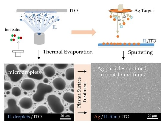
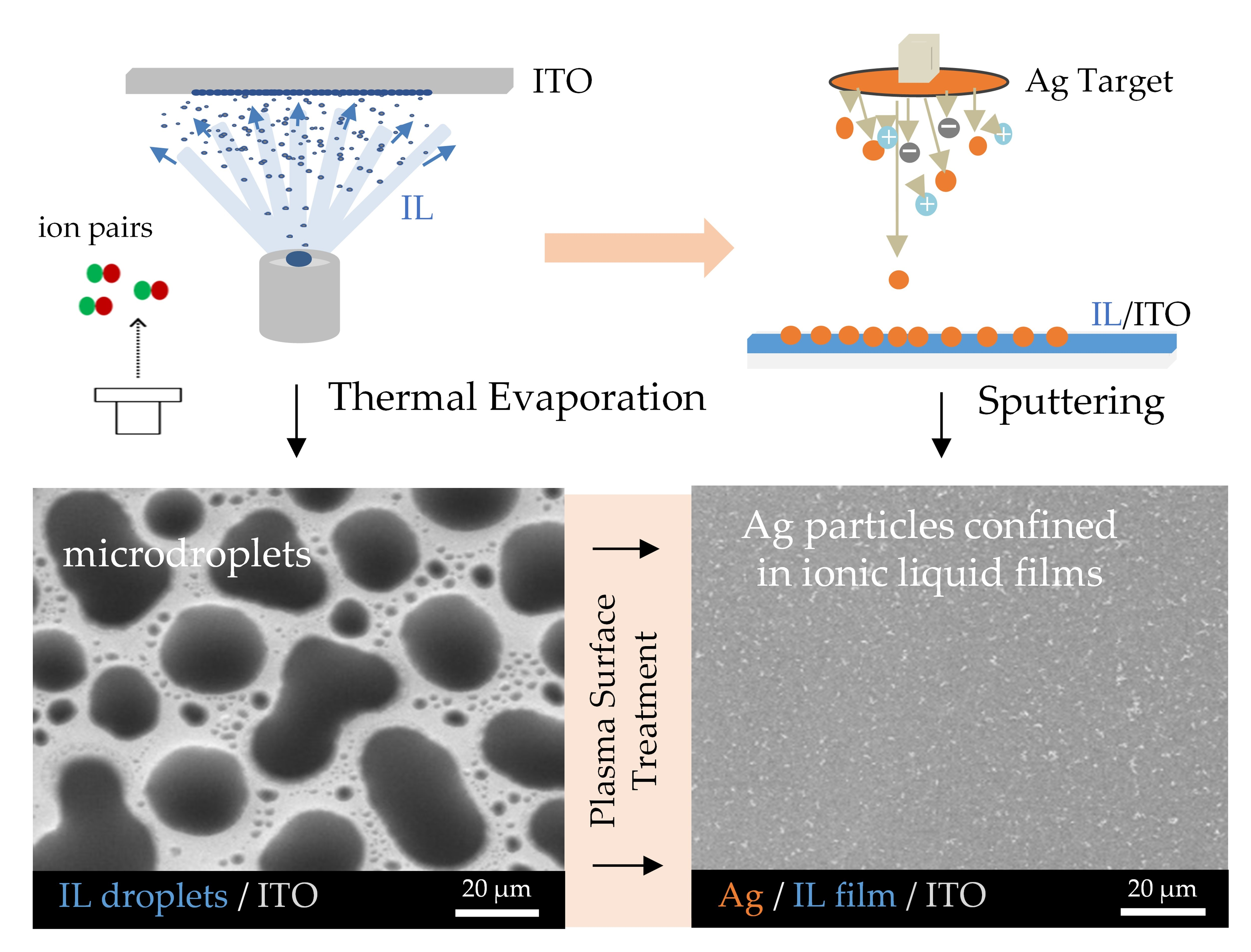
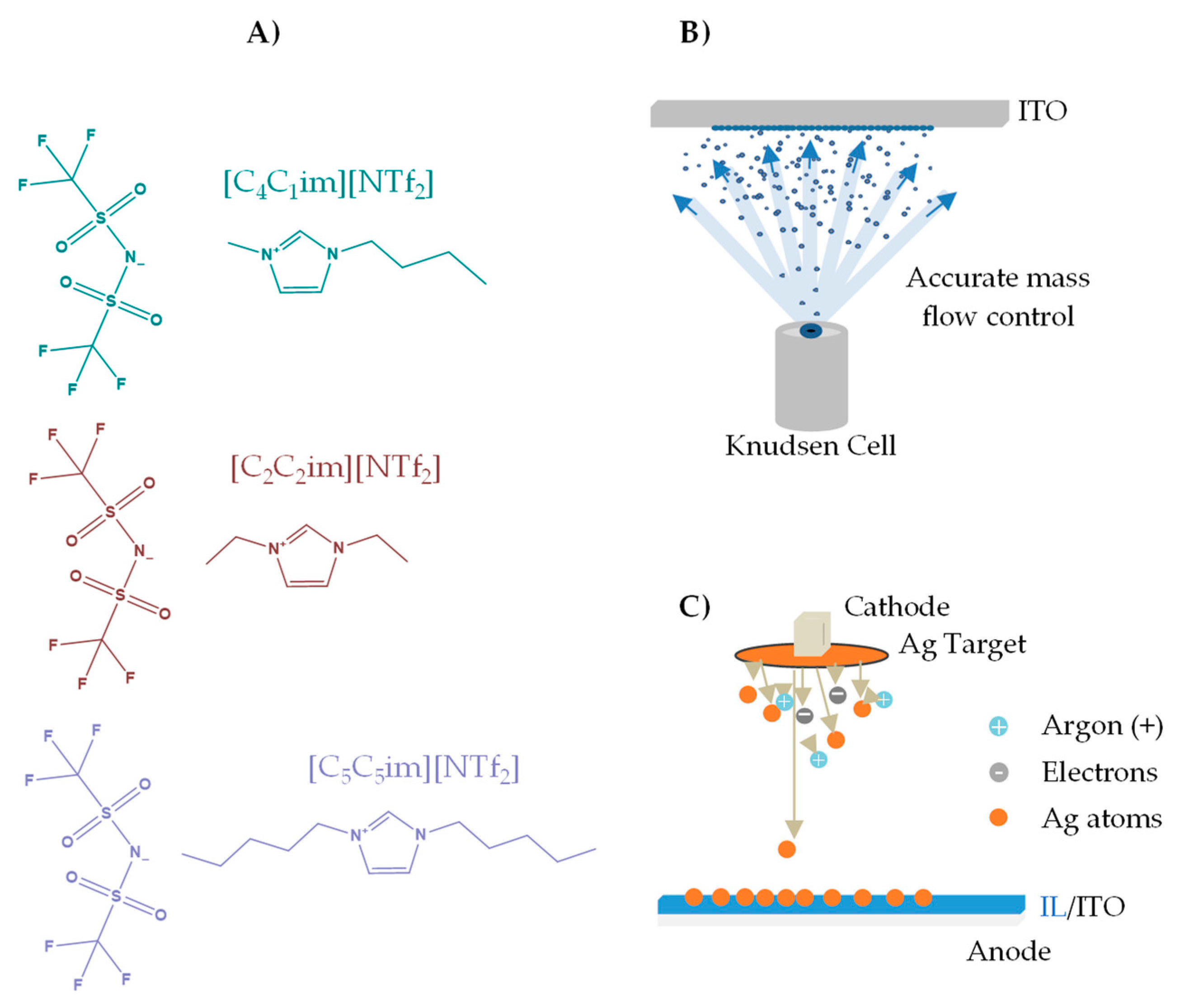
:
1. Introduction
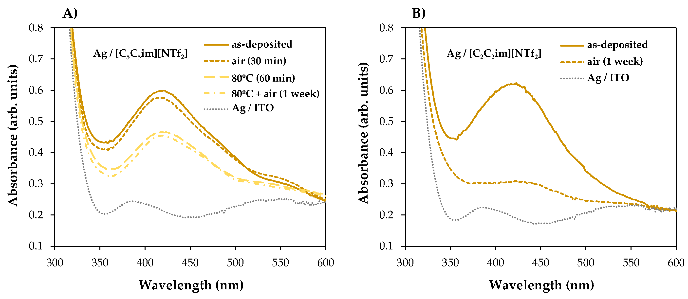
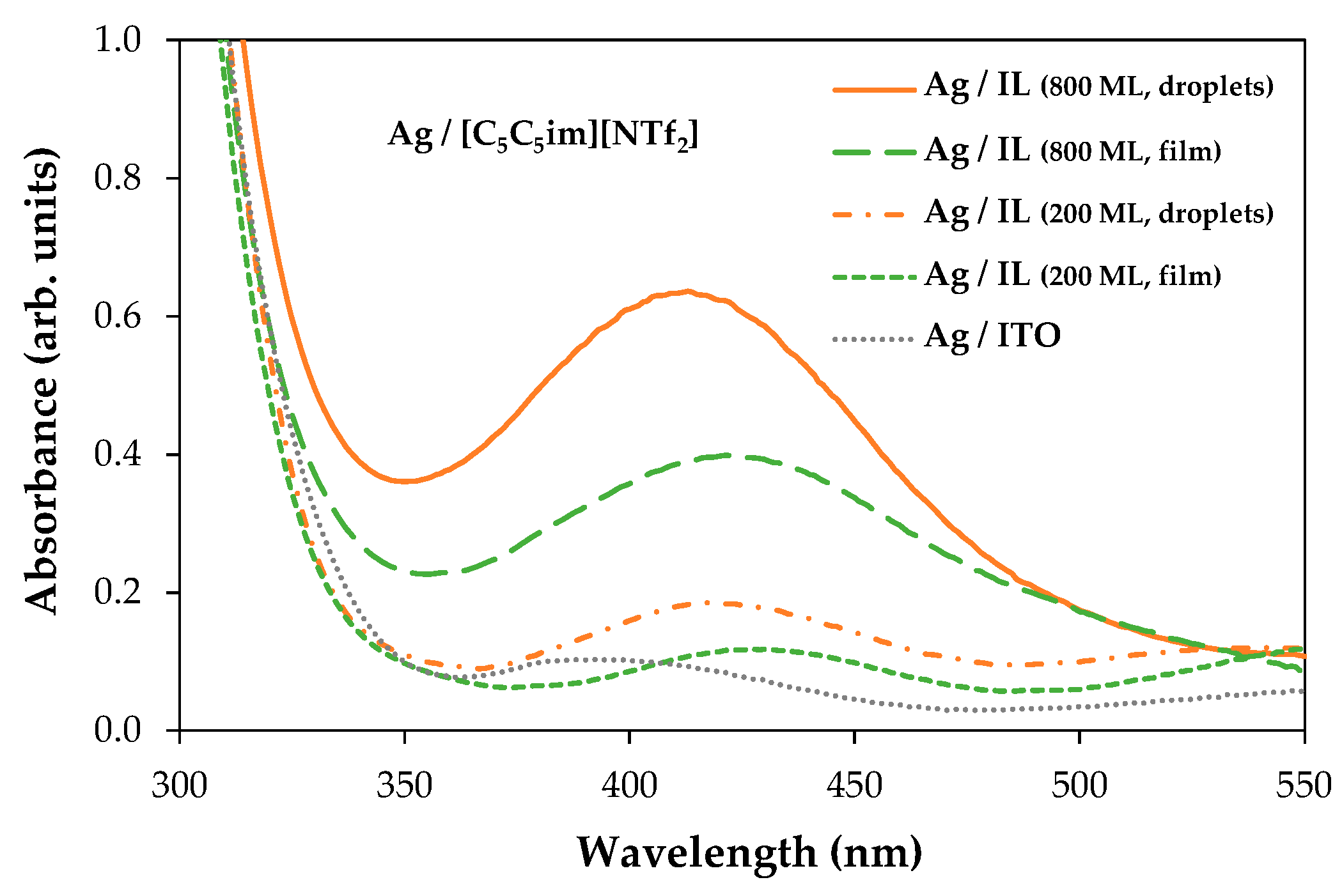
2. Results
3. Discussion
4. Materials and Methods
4.1. Ionic Liquids
4.2. Vacuum Thermal Evaporation of Ionic Liquids
4.3. Sputter Deposition of Silver Particles in ILs
4.4. High-Resolution Scanning Electron Microscopy
4.5. UV-Vis Spectroscopy
5. Conclusions
Supplementary Materials
Author Contributions
Funding
Institutional Review Board Statement
Informed Consent Statement
Data Availability Statement
Acknowledgments
Conflicts of Interest
References
- Torimoto, T.; Okazaki, K.I.; Kiyama, T.; Hirahara, K.; Tanaka, N.; Kuwabata, S. Sputter Deposition onto Ionic Liquids: Simple and Clean Synthesis of Highly Dispersed Ultrafine Metal Nanoparticles. Appl. Phys. Lett. 2006, 89, 243117. [Google Scholar] [CrossRef]
- Vanecht, E.; Binneamans, K.; Seo, J.W.; Stappers, L.; Fransaer, J. Growth of Sputter-Deposited Gold Nanoparticles in Ionic Liquids. Phys. Chem. Chem. Phys. 2011, 13, 13565–13571. [Google Scholar] [CrossRef] [Green Version]
- Vanecht, E.; Binneamans, K.; Patskovsky, S.; Meunier, M.; Seo, J.W.; Stappers, L.; Fransaer, J. Stability of Sputter-Deposited Gold Nanoparticles in Imidazolium Ionic Liquids. Phys. Chem. Chem. Phys. 2012, 14, 5662–5671. [Google Scholar] [CrossRef] [Green Version]
- Suzuki, S.; Suzuki, T.; Tomita, Y.; Hirano, M.; Okasaki, K.-I.; Kuwabata, S.; Torimoto, T. Compositional Control of AuPt Nanoparticles Synthesized in Ionic Liquids by the Sputter Deposition Technique. CrystEngComm 2012, 14, 4922–4926. [Google Scholar] [CrossRef]
- Meischein, M.; Wang, X.; Ludwig, A. Unraveling the Formation Mechanism of Nanoparticles Sputtered in Ionic Liquid. J. Phys. Chem. C 2021, 125, 24229–24239. [Google Scholar] [CrossRef]
- Nguyen, M.T.; Deng, L.; Yonezawa, T. Control of Nanoparticles Synthesized via Vacuum Sputter Deposition onto Liquids: A Review. Soft Matter 2022, 18, 19–47. [Google Scholar] [CrossRef] [PubMed]
- Baptista, A.; Silva, F.; Porteiro, J.; Míguez, J.; Pinto, G. Sputtering Physical Vapour Deposition (PVD) Coatings: A Critical Review on Process Improvement and Market Trend Demands. Coatings 2018, 8, 402. [Google Scholar] [CrossRef] [Green Version]
- Kelly, P.J.; Arnell, R.D. Magnetron Sputtering: A Review of Recent Developments and Applications. Vacuum 2000, 56, 159–172. [Google Scholar] [CrossRef]
- Nguyen, M.T.; Yonezawa, T. Sputtering onto a Liquid: Interesting Physical Preparation Method for Multi-Metallic Nanoparticles. Sci. Technol. Adv. Mater. 2018, 19, 883–898. [Google Scholar] [CrossRef] [Green Version]
- Sergievskaya, A.; Chauvin, A.; Konstantinidis, S. Sputtering onto Liquids: A Critical Review. Beilstein J. Nanotechnol. 2022, 13, 10–53. [Google Scholar] [CrossRef] [PubMed]
- Wender, H.; Migowski, P.; Feil, A.F.; Teixeira, S.R.; Dupont, J. Sputtering Deposition of Nanoparticles onto Liquid Substrates: Recent Advances and Future Trends. Coord. Chem. Rev. 2013, 257, 2468–2483. [Google Scholar] [CrossRef]
- Iqbal, S.; Bahadur, A.; Ali, S.; Ahmad, Z.; Javed, M.; Irfan, R.M.; Ahmad, N.; Qamar, M.A.; Liu, G.; Akbar, M.B.; et al. Critical Role of the Heterojunction Interface of Silver Decorated ZnO Nanocomposite with Sulfurized Graphitic Carbon Nitride Heterostructure Materials for Photocatalytic Applications. J. Alloys Compd. 2021, 858, 158338. [Google Scholar] [CrossRef]
- Iqbal, S.; Ahmad, N.; Javed, M.; Qamar, M.A.; Bahadur, A.; Ali, S.; Ahmad, Z.; Irfan, R.M.; Liu, G.; Akbar, M.B.; et al. Designing Highly Potential Photocatalytic Comprising Silver Deposited ZnO NPs with Sulfurized Graphitic Carbon Nitride (Ag/ZnO/S-g-C3N4) Ternary Composite. J. Environ. Chem. Eng. 2021, 9, 104919. [Google Scholar] [CrossRef]
- Rashed, M.A.; Ahmed, J.; Faisal, M.; Alsareii, S.A.; Jalalah, M.; Harraz, F.A. Highly Sensitive and Selective Thiourea Electrochemical Sensor Based on Novel Silver Nanoparticles/Chitosan Nanocomposite. Colloids Surf. A Physicochem. Eng. Asp. 2022, 644, 128879. [Google Scholar] [CrossRef]
- Khodashenas, B.; Ghorbani, H.R. Synthesis of Silver Nanoparticles with Different Shapes. Arab. J. Chem. 2019, 12, 1823–1838. [Google Scholar] [CrossRef] [Green Version]
- Kuntyi, O.I.; Kytsya, A.R.; Mertsalo, I.P.; Mazur, A.S.; Zozula, G.I.; Bazylyak, L.I.; Topchak, R.V. Electrochemical Synthesis of Silver Nanoparticles by Reversible Current in Solutions of Sodium Polyacrylate. Colloid Polym. Sci. 2019, 297, 689–695. [Google Scholar] [CrossRef]
- Slepicka, P.; Kasalkova, N.S.; Siegel, J.; Kolska, Z.; Svorcik, V. Methods of Gold and Silver Nanoparticles Preparation. Materials 2020, 12, 1. [Google Scholar] [CrossRef] [PubMed] [Green Version]
- Jamkhande, P.G.; Ghule, N.W.; Bamer, A.H.; Kalaskar, M.G. Metal Nanoparticles Synthesis: An Overview on Methods of Preparation, Advantages and Disadvantages, and Applications. J. Drug Deliv. Sci. Technol. 2019, 53, 101174. [Google Scholar] [CrossRef]
- Wisz, G.; Potera, P.; Sawicka-Chudy, P.; Gwozdz, K. Optical Properties of ITO/Glass Substrates Modified by Silver Nanoparticles for PV Applications. Coatings 2023, 13, 161. [Google Scholar] [CrossRef]
- Torimoto, T.; Tsuda, T.; Okazaki, K.-I.; Kuwabata, S. New Frontiers in Materials Science Opened by Ionic Liquids. Adv. Mater. 2010, 22, 1196–1221. [Google Scholar] [CrossRef]
- Costa, J.C.S.; Alves, A.; Bastos, M.; Santos, L.M.N.B.F. The Impact of the Cation Alkyl Chain Length on the Wettability of Alkylimidazolium-Based Ionic Liquids at the Nanoscale. Phys. Chem. Chem. Phys. 2022, 14, 13343–13355. [Google Scholar] [CrossRef]
- Costa, J.C.S.; Mendes, A.; Santos, L.M.N.B.F. Morphology of Imidazolium-Based Ionic Liquids as Deposited by Vapor Deposition: Micro-/Nanodroplets and Thin Films. ChemPhysChem 2016, 17, 2123–2127. [Google Scholar] [CrossRef] [Green Version]
- Costa, J.C.S.; Coelho, A.F.S.M.G.; Mendes, A.; Santos, L.M.N.B.F. Nucleation and Growth of Microdroplets of Ionic Liquids Deposited by Physical Vapor Method onto Different Surfaces. Appl. Surf. Sci. 2018, 428, 242–249. [Google Scholar] [CrossRef]
- Teixeira, M.S.M.; Santos, L.M.N.B.F.; Costa, J.C.S. Nucleation, Coalescence, and Thin-Film Growth of Triflate-Based Ionic Liquids on ITO, Ag, and Au Surfaces. Colloids Interfaces 2022, 6, 46. [Google Scholar] [CrossRef]
- Bermúdez, M.-D.; Jiménez, A.-E.; Sanes, J.; Carrión, F.-J. Ionic Liquids as Advanced Lubricant Fluids. Molecules 2009, 14, 2888–2908. [Google Scholar] [CrossRef] [PubMed]
- Pei, Y.; Zhang, Y.; Ma, J.; Fan, M.; Zhang, S.; Wang, J. Ionic Liquids for Advanced Materials. Mater. Today Nano 2022, 17, 100159. [Google Scholar] [CrossRef]
- Wishart, J.F. Energy Applications of Ionic Liquids. Energy Environ. Sci. 2009, 2, 956–961. [Google Scholar] [CrossRef]
- Plechkova, N.V.; Seddon, K.R. Applications of Ionic Liquids in the Chemical Industry. Chem. Soc. Rev. 2008, 37, 123–150. [Google Scholar] [CrossRef] [PubMed]
- Hayes, R.; Warr, G.G. Structure and Nanostructure in Ionic Liquids. Chem. Rev. 2015, 115, 6357–6426. [Google Scholar] [CrossRef] [Green Version]
- Canongia Lopes, J.N.A.; Pádua, A.A.H. Nanostructural Organization in Ionic Liquids. J. Phys. Chem. B 2006, 110, 3330–3335. [Google Scholar] [CrossRef] [PubMed]
- Del Pópolo, M.G.; Voth, G.A. On the Structure and Dynamics of Ionic Liquids. J. Phys. Chem. B 2004, 108, 1744–1752. [Google Scholar] [CrossRef]
- Almeida, H.F.D.; Freire, M.G.; Fernandes, A.M.; Lopes-da-Silva, J.A.; Morgado, P.; Shimizu, K.; Filipe, E.J.M.; Canongia Lopes, J.N.; Santos, L.M.N.B.F.; Coutinho, J.A.P. Cation Alkyl Side Chain Length and Symmetry Effects on the Surface Tension of Ionic Liquids. Langmuir 2014, 30, 6408–6418. [Google Scholar] [CrossRef] [PubMed]
- Liu, H.; Jiang, L. Wettability by Ionic Liquids. Small 2016, 12, 9–15. [Google Scholar] [CrossRef] [PubMed]
- Minea, A.A.; Murshed, S.M.S. A Review on Development of Ionic Liquid Based Nanofluids and their Heat Transfer Behavior. Renew. Sustain. Energy Rev. 2018, 91, 584–599. [Google Scholar] [CrossRef]
- Yebra, F.; Troncoso, J.; Romaní, K. Thermal Conductivity of Ionic Liquids under Pressure. Fluid Phase Equil. 2020, 515, 112573. [Google Scholar] [CrossRef]
- Kaur, G.; Kumar, H.; Singla, M. Diverse Applications of Ionic Liquids: A Comprehensive Review. J. Mol. Liq. 2022, 351, 118556. [Google Scholar] [CrossRef]
- Wender, H.; De Oliveira, L.F.; Migowski, P.; Feil, A.F.; Lissner, E.; Prechtl, M.H.G.; Teixeira, S.R.; Dupont, J. Ionic Liquid Surface Composition Controls the Size of Gold Nanoparticles Prepared by Sputtering Deposition. J. Phys. Chem. C 2010, 114, 11764–11768. [Google Scholar] [CrossRef] [Green Version]
- Patil, A.B.; Bhanage, B.M. Shape Selectivity Using Ionic Liquids for the Preparation of Silver and Silver Sulphide Nanomaterials. Phys. Chem. Chem. Phys. 2014, 16, 3027–3035. [Google Scholar] [CrossRef]
- Avirdi, E.; Paumo, H.K.; Kamdem, B.P.; Singh, M.B.; Kumari, K.; Katata-Seru, L.M.; Bahadur, I. Influence of Cation (Imidazolium Based Ionic Liquids) as “Smart” Stabilizers for Silver Nanoparticles and their Evaluation as Antibacterial Activity on Escherichia Coli, Staphylococcus Aureus and Enterobacter Cloacae. J. Mol. Liq. 2023, 369, 120935. [Google Scholar] [CrossRef]
- Verma, C.; Ebenso, E.E.; Quraishi, M.A. Transition Metal Nanoparticles in Ionic Liquids: Synthesis and Stabilization. J. Mol. Liq. 2019, 276, 826–829. [Google Scholar] [CrossRef]
- Seitkalieva, M.M.; Samoylenko, D.E.; Lotsman, K.A.; Rodygin, K.S.; Ananikov, V.P. Metal Nanoparticles in Ionic Liquids: Synthesis and Catalytic Applications. Coord. Chem. Rev. 2021, 445, 213982. [Google Scholar] [CrossRef]
- Garg, G.; Foltran, S.; Favier, I.; Pla, D.; Medina-Gonzaléz, Y.; Gómez, M. Palladium Nanoparticles Stabilized by Novel Choline-Based Ionic Liquids in Glycerol Applied in Hydrogenation Reactions. Catal. Today 2020, 346, 69–75. [Google Scholar] [CrossRef]
- Schmolke, L.; Lerch, S.; Bulow, M.; Siebels, M.; Schmitz, A.; Thomas, J.; Dehm, G.; Held, C.; Strassner, T.; Janiak, C. Aggregation Control of Ru and Ir Nanoparticles by Tunable Aryl Alkyl Imidazolium Ionic Liquids. Nanoscale 2019, 11, 4073–4082. [Google Scholar] [CrossRef] [PubMed]
- Guo, X.; Peng, Z.; Traitangwong, A.; Wang, G.; Xu, H.; Meeyoo, V.; Li, C.; Zhang, S. Ru Nanoparticles Stabilized by Ionic Liquids Supported onto Silica: Highly Active Catalysts for Low-Temperature CO2 Methanation. Green Chem. 2018, 20, 4932–4945. [Google Scholar] [CrossRef]
- Schmitz, A.; Meyer, H.; Meischein, M.; Manjón, A.G.; Schmolke, L.; Giesen, B.; Schlusener, C.; Simon, P.; Grin, Y.; Fischer, R.A.; et al. Synthesis of Plasmonic Fe/Al Nanoparticles in Ionic Liquids. RSC Adv. 2020, 10, 12891–12899. [Google Scholar] [CrossRef]
- Qadir, M.I.; Kauling, A.; Calabria, L.; Grehl, T.; Dupont, J. Fabrication of Naked Silver Nanoparticles in Functionalized Ionic Liquids. Nano-Struct. Nano-Objects 2018, 14, 92–97. [Google Scholar] [CrossRef]
- He, Z.; Alexandrilis, P. Nanoparticles in Ionic Liquids: Interactions and Organization. Phys. Chem. Chem. Phys. 2015, 17, 18238–18261. [Google Scholar] [CrossRef]
- Campos, R.M.; Alves, A.C.P.M.; Lima, M.A.L.; Farinha, A.F.M.; Cardoso, J.P.S.; Mendes, A.; Costa, J.C.S.; Santos, L.M.N.B.F. Morphology, Structure, and Dynamics of Pentacene Thin Films and Their Nanocomposites with [C2C1im][NTf2] and [C2C1im][OTF] Ionic Liquids. ChemPhysChem 2020, 21, 1814–1825. [Google Scholar] [CrossRef] [PubMed]
- Lexow, M.; Maier, F.; Steinruck, H.-P. Ultrathin Ionic Liquid Films on Metal Surfaces: Adsorption, Growth, Stability and Exchange Phenomena. Adv. Phys. X 2020, 5, 1761266. [Google Scholar] [CrossRef]
- Cai, M.; Yu, Q.; Liu, W.; Zhou, F. Ionic Liquid Lubricants: When Chemistry Meets Tribology. Chem. Soc. Rev. 2020, 49, 7753–7818. [Google Scholar] [CrossRef] [PubMed]
- Lexow, M.; Talwar, T.; Heller, B.S.-J.; May, B.; Bhuin, R.G.; Maier, F.; Steinruck, H.-P. Time-Dependent Changes in the Growth of Ultrathin Ionic Liquid Films on Ag(111). Phys. Chem. Chem. Phys. 2018, 20, 12929–12938. [Google Scholar] [CrossRef] [PubMed] [Green Version]
- Borghi, F.; Mirigliano, M.; Lenardi, C.; Milani, P.; Podestà, A. Nanostructure Determines the Wettability of Gold Surfaces by Ionic Liquid Ultrathin Films. Front. Chem. 2021, 9, 619432. [Google Scholar] [CrossRef] [PubMed]
- Zhao, Q.; Bennington, P.; Nealey, P.F.; Patel, S.N.; Evans, C.M. Ion Specific, Thin Film Confinement Effects on Conductivity in Polymerized Ionic Liquids. Macromolecules 2021, 54, 10520–10528. [Google Scholar] [CrossRef]
- Borghi, F.; Podestà, A. Ionic Liquids under Nanoscale Confinement. Adv. Phys. X 2020, 5, 1736949. [Google Scholar] [CrossRef] [Green Version]
- Obst, M.; Arnauts, G.; Cruz, A.J.; Gonzalez, M.C.; Marcoen, K.; Hauffman, T.; Ameloot, R. Chemical Vapor Deposition of Ionic Liquids for the Fabrication of Ionogel Films and Patterns. Angew. Chem. Int. Ed. 2021, 60, 25668–25673. [Google Scholar] [CrossRef] [PubMed]
- Calabria, L.; Fernandes, J.A.; Migowski, P.; Bernardi, F.; Baptista, D.L.; Leal, R.; Grehl, T.; Dupont, J. Confined Naked Gold Nanoparticles in Ionic Liquid Films. Nanoscale 2017, 9, 18753–18758. [Google Scholar] [CrossRef]
- Dupont, J.; Fonseca, G.S.; Umpierre, A.P.; Fichtner, P.F.P.; Teixeira, S.R. Transition-Metal Nanoparticles in Imidazolium Ionic Liquids: Recycable Catalysts for Biphasic Hydrogenation Reactions. J. Am. Chem. Soc. 2002, 124, 4228–4229. [Google Scholar] [CrossRef] [PubMed]
- Dupont, J.; Scholten, J.D. On the Structural and Surface Properties of Transition-Metal Nanoparticles in Ionic Liquids. Chem. Soc. Rev. 2010, 39, 1780–1804. [Google Scholar] [CrossRef] [PubMed]
- Dong, K.; Zhang, S. Hydrogen Bonds: A Structural Insight into Ionic Liquids. Chem. Eur. J. 2012, 18, 2748–2761. [Google Scholar] [CrossRef] [PubMed]
- Castner, E.W.; Wishart, J.F.; Shirota, H. Intermolecular Dynamics, Interactions, and Solvation in Ionic Liquids. Acc. Chem. Res. 2007, 40, 1217–1227. [Google Scholar] [CrossRef] [PubMed]
- Migowski, P.; Dupont, J. Catalytic Applications of Metal Nanoparticles in Imidazolium Ionic Liquids. Chem. Eur. J. 2007, 13, 32–39. [Google Scholar] [CrossRef]
- Wang, L.; Chang, L.; Zhao, B.; Yuan, Z.; Shao, G.; Zheng, W. Systematic Investigation on Morphologies, Forming Mechanism, Photocatalytic and Photoluminescent Properties of ZnO Nanostructures Constructed in Ionic Liquids. Inorg. Chem. 2008, 47, 1443–1452. [Google Scholar] [CrossRef]
- Samari, F.; Dorostkar, S. Synthesis of Highly Stable Silver Nanoparticles Using Imidazolium-Based Ionic Liquid. J. Iran. Chem. Soc. 2016, 13, 689–693. [Google Scholar] [CrossRef]
- Costa, J.C.S.; Campos, R.M.; Castro, A.C.M.; Farinha, A.F.M.; Oliveira, G.N.P.; Araújo, J.P.; Santos, L.M.N.B.F. The Effect of Ionic Liquids on the Nucleation and Growth of Perylene Films Obtained by Vapor Deposition. CrystEngComm 2023, 25, 913–924. [Google Scholar] [CrossRef]
- McLeod, M.C.; McHenry, R.S.; Beckman, E.J.; Roberts, C.B. Synthesis and Stabilization of Silver Metallic Nanoparticles and Premetallic Intermediates in Perfluoropolyether/CO2 Reverse Micelle Systems. J. Phys. Chem. B 2003, 107, 2693–2700. [Google Scholar] [CrossRef]
- Khanh Vu, N.; Zille, A.; Oliveira, F.R.; Carneiro, N.; Souto, A.P. Effect of Particle Size on Silver Nanoparticle Deposition onto Dielectric Barrier Discharge (DBD) Plasma Functionalized Polyamide Fabric. Plasma Process. Polym. 2013, 10, 285–296. [Google Scholar]
- Xia, Y.; Halas, N.J. Shape-Controlled Synthesis and Surface Plasmonic Properties of Metallic Nanostructures. MRS Bull. 2005, 30, 338–348. [Google Scholar] [CrossRef] [Green Version]
- Wegner, S.; Janiak, C. Metal Nanoparticles in Ionic Liquids. Top Curr. Chem. (Z) 2017, 375, 65. [Google Scholar] [CrossRef]
- Cutolo, A.; Pagliarulo, V.; Merola, F.; Coppola, S.; Ferraro, P.; Fraldi, M. Wrinkling Prediction, Formation and Evolution in Thin Films Adhering on Polymeric Substrata. Mater. Des. 2020, 187, 108314. [Google Scholar] [CrossRef]
- Chen, C.M.; Yang, S. Wrinkling Instabilities in Polymer Films and their Applications. Polym. Int. 2012, 61, 1041–1047. [Google Scholar] [CrossRef]
- Yu, S.; Sun, Y.; Ni, Y.; Zhang, X.; Zhou, H. Controlled Formation of Surface Patterns in Metal Films Deposited on Elasticity-Gradient PDMS Substrates. ACS Appl. Mater. Interfaces 2016, 8, 5706–5714. [Google Scholar] [CrossRef] [PubMed]
- Ma, L.; He, L.; Ni, Y. Tunable Hierarchical Wrinkling: From Models to Applications. J. Appl. Phys. 2020, 127, 111101. [Google Scholar] [CrossRef]
- Hatakeyama, Y.; Takahashi, S.; Nishikawa, K. Can Temperature Control the Size of Au Nanoparticles Prepared in Ionic Liquids by the Sputter Deposition Technique? J. Phys. Chem. C 2010, 114, 11098–11102. [Google Scholar] [CrossRef]
- Kameyama, T.; Ohno, Y.; Kurimoto, T.; Okazaki, K.I.; Uematsu, T.; Kuwabata, S.; Torimoto, T. Size Control and Immobilization of Gold Nanoparticles Stabilized in an Ionic Liquid on Glass Substrates for Plasmonic Applications. Phys. Chem. Chem. Phys. 2010, 12, 1804–1811. [Google Scholar] [CrossRef]
- Costa, J.C.S.; Rocha, R.M.; Vaz, I.C.M.; Torres, M.C.; Mendes, A.; Santos, L.M.N.B.F. Description and Test of a New Multilayer Thin Film Vapor Deposition Apparatus for Organic Semiconductor Materials. J. Chem. Eng. Data 2015, 60, 3776–3791. [Google Scholar] [CrossRef] [Green Version]
- Rietzler, F.; May, B.; Steinruck, H.-P.; Maier, F. Switching Adsorption and Growth Behavior of Ultrathin [C2C1Im][OTf] Films on Au(111) by Pd Deposition. Phys. Chem. Chem. Phys. 2016, 18, 25143–25150. [Google Scholar] [CrossRef] [Green Version]
- Rocha, M.A.A.; Neves, C.M.S.S.; Freire, M.G.; Russina, O.; Triolo, A.; Coutinho, J.A.P.; Santos, L.M.N.B.F. Alkylimidazolium Based Ionic Liquids: Impact of Cation Symmetry on their Nanoscale Structural Organization. J. Phys. Chem. B 2013, 117, 10889–10897. [Google Scholar] [CrossRef] [PubMed]


Disclaimer/Publisher’s Note: The statements, opinions and data contained in all publications are solely those of the individual author(s) and contributor(s) and not of MDPI and/or the editor(s). MDPI and/or the editor(s) disclaim responsibility for any injury to people or property resulting from any ideas, methods, instructions or products referred to in the content. |
© 2023 by the authors. Licensee MDPI, Basel, Switzerland. This article is an open access article distributed under the terms and conditions of the Creative Commons Attribution (CC BY) license (https://creativecommons.org/licenses/by/4.0/).
Share and Cite
Alves, A.C.P.M.; Santos, L.M.N.B.F.; Bastos, M.; Costa, J.C.S. Confined Silver Nanoparticles in Ionic Liquid Films. Molecules 2023, 28, 3029. https://doi.org/10.3390/molecules28073029
Alves ACPM, Santos LMNBF, Bastos M, Costa JCS. Confined Silver Nanoparticles in Ionic Liquid Films. Molecules. 2023; 28(7):3029. https://doi.org/10.3390/molecules28073029
Chicago/Turabian StyleAlves, Alexandre C. P. M., Luís M. N. B. F. Santos, Margarida Bastos, and José C. S. Costa. 2023. "Confined Silver Nanoparticles in Ionic Liquid Films" Molecules 28, no. 7: 3029. https://doi.org/10.3390/molecules28073029