
Joint Design of Polar Coding and Physical Network Coding for Two−User Downlink Non−Orthogonal Multiple Access

1
College of Physics and Information Engineering, Fuzhou University, Fuzhou 350108, China
2
College of Computer Science, Chongqing University, Chongqing 400044, China
*
Author to whom correspondence should be addressed.
Entropy 2023, 25(2), 233; https://doi.org/10.3390/e25020233
Submission received: 11 December 2022
/
Revised: 16 January 2023
/
Accepted: 19 January 2023
/
Published: 27 January 2023
(This article belongs to the Special Issue Advances in Multiuser Information Theory)
Abstract
:In this paper, we propose a joint polar coding and physical network coding (PNC) for two−user downlink non−orthogonal multiple access (PN−DNOMA) channels, since the successive–interference–cancellation–aided polar decoding cannot be optimal for finite blocklength transmissions. In the proposed scheme, we first constructed the XORed message of two user messages. Then, the XORed message was superimposed with the message of the weak User 2 for broadcast. By doing so, we can utilize the PNC mapping rule and polar decoding to directly recover the message of User 1, while at User 2, we equivalently constructed a long−length polar decoder to obtain its user message. The channel polarization and decoding performance can be greatly improved for both users. Moreover, we optimized the power allocation of the two users with their channel conditions by considering the user fairness and the performance. The simulation results showed that the proposed PN−DNOMA can achieve performance gains of about 0.4−0.7 dB over the conventional schemes in two−user downlink NOMA systems.
1. Introduction
Non-orthogonal multiple access (NOMA) is a promising multiple access technique in 5G communications to increase system throughput and accommodate massive connectivity [1]. Compared to traditional orthogonal multiple access (OMA), NOMA allows multiple users to simultaneously transmit signals using the same time/frequency radio resources, but different power levels [2]. The key advantage of NOMA is exploring the extra power domain to further increase the number of supportable users. Specifically, users are identified by their channel conditions. Those with good channel conditions are called strong users, and the others are called weak users [3]. For the sake of fairness, less power is allocated to strong users at the transmitter side. In this way, the transmitter sends the superposition of signals with different power levels, and the receiver applies successive interference cancellation (SIC) to strong users to realize multi-user detection. Consider a typical NOMA system, which consists of a base station (BS) and two user nodes. Ref. [4] proposed power allocation (PA) algorithms to maximize the ergodic capacity under the power and rate constraints of the weak user. With fixed power coefficients, Ref. [5] considered the exact bit error rate (BER) analysis of a two-user NOMA system using square quadrature amplitude modulation (QAM). Ref. [6] proposed a joint adaptive M-QAM modulation and power adaptation. While the BS is equipped with multiple antennas, Ref. [7] proposed a matched-filter (MF) preceding algorithm and analyzed the required power consumption under SINR constraints for both users, as well as the power-outage tradeoff. Ref. [8] analyzed the quasi-degradation probability and proposed an analytical framework to characterize the optimality of NOMA over Rician fading channels. Moreover, Reference [9] investigated the achievable rate region in the large-system limit of regular sparse NOMA with two users. Given a minimum target rate for the individual users, Reference [10] analyzed the outage probability with respect to the total data rates.
In conventional NOMA systems, the SIC is employed for signal decoding, which is optimal for sufficient long blocklength transmissions [11]. However, for finite blocklength transmissions, the joint decoding instead of SIC has been shown to be better [12]. By using the random channel coding theorem, Reference [13] proposed a NOMA implementation without SIC and proved that the conditional achievable sum rate given channel gains can be achieved by this scheme. Polar code, proposed by Arikan in 2006, can achieve the symmetric channel capacity of binary discrete memoryless channels under a successive cancellation (SC) or a cyclic−redundancy−check−aided SC−list (CA−SCL) decoder, as the code length goes to infinity [14]. Considering the decoding error probability and PA optimization, a joint polar decoding and SIC decoding strategy (PC−SIC) was proposed [12]. PC-SIC aims to maximize the effective throughput at the central user under the minimum required effective throughput constraint at the cell edge user. However, this scheme mainly considers the individual decoding by users, and the superposition of signals is performed to ensure that the inter-user interference can be successfully removed by SIC at the receiver.
Moreover, the physical-layer network coding (PNC) can significantly enhance the spectrum efficiency and the network throughput by utilizing network interference [15,16]. The concept of PNC lies in that the relay maps the overlapped received signals from two users to a network coding (NC) message. The channel coding and efficient decoding were developed for polar-coded PNC [17]. Network-coded multiple access (NCMA) was proposed for NOMA systems [18], which estimates an NC message and then a single-user message.
In this paper, by exploiting the principles of the polar code and PNC, we propose a joint polar coding and PNC over two-user downlink NOMA (PN−DNOMA) systems, which can convert the inter-user interference into a useful message. In particular, User 1 can use the PNC mapping rule for direct decoding, while User 2 can construct a longer-length decoder from the received signal, and the channel polarization effect can be greatly improved. In the proposed scheme, the BS transmits the superimposed message of the XORed message of two users and the message of the weak User 2. This is different from the conventional downlink NOMA schemes, where the superimposed message of two users is broadcast [19]. Then, we can directly recover the message of User 1 aided by PNC mapping from the received signal, and the message of User 2 is estimated by using a constructed long−length polar decoder. In addition, we determined the optimal power allocation of the two users given the channel condition to improve the user fairness and performance. The simulation results showed that the proposed PN−DNOMA can achieve performance gains of about 0.4–0.7 dB over the conventional PC−SIC in the two-user downlink NOMA system.
2. Background and System Model
2.1. System Model
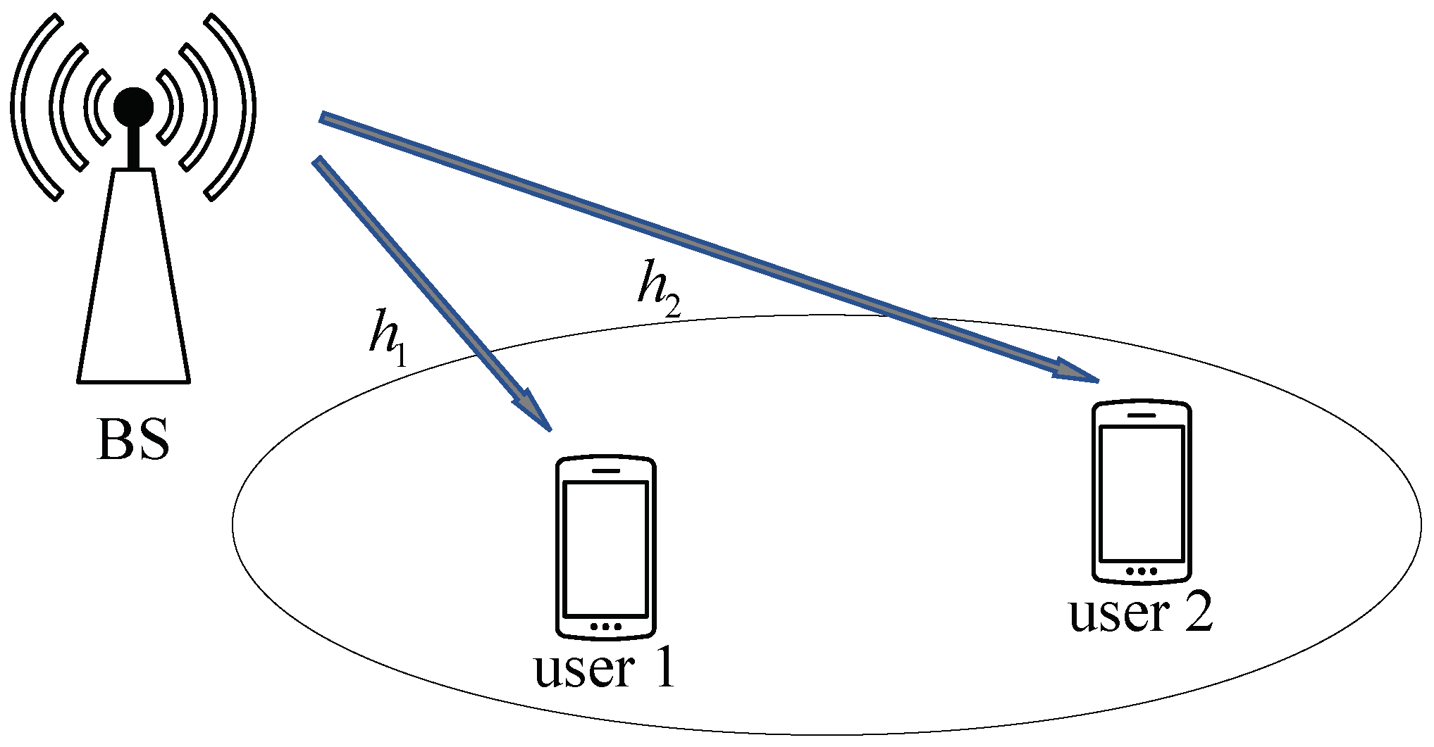
We considered a downlink NOMA system with two user nodes and a BS, as shown in Figure 1. The channel gain from the BS to user s is expressed as , . In particular, , with being the distance from the BS to the user s, where is the loss exponent and [20]. Without loss of generality, we assumed that User 1 and User 2 are the strong user and weak user from the BS, respectively. In this paper, for convenience, we use the notation to denote a sequence and to denote the v-th message in the superimposed signal, . Let denote the source bits of length Z from the BS sent to user s, . After polar encoding for , we can have the length−Z codeword of user s. In the conventional downlink NOMA [21], the two-user codewords are modulated and superimposed at the BS, then broadcast to the two users.
In this paper, at the BS, we first obtain the XORed message . For notational simplicity, we denote the message of User 2 by . Afterward, is the BPSK modulated to the signal , . Then, we can construct the superimposed signal of the XORed and the message for broadcast. The received signal at the user s can be given by
where denotes the transmit power for , subjected to the total transmit power , i.e., and . w denotes a Gaussian random noise with variance , between user s and the BS. are assumed to be known at the BS, which may be obtained by a feedback channel from the users [22].
2.2. Channel Polarization
Let denote a binary-input discrete memoryless channel (B-DMC) with the input alphabet , output alphabet , and channel transition probabilities . For a length-N polar code, the source block consists of information bits and frozen bits , where denotes information bits and denotes frozen bits. In this paper, we adopted a systematic polar code [23], and the code bits , , given by
where is the N-dimensional generator matrix and , where ⊗ denotes the Kronecker product , . The channels are merged and split into bit-channels , . Let denote the i−th channel transition probability with input bit and outputs , given by
The K most-reliable split bit−channels are determined to transmit the information bits, and the rest are used as frozen bits, i.e., zeros. The decoder calculates the LLR of the i-th bit as
where is the estimation of the vector . During the decoding, the LLRs for odd channels and for even channels can be, respectively, computed via recursion:
and
where and are the subvectors of estimated bits with odd and even indices, respectively. The box−plus operation ⊞ is defined as [24].
3. Polar Coded for NOMA
3.1. Proposed PN-DNOMA Scheme
Recall that the encoding matrix can be obtained by the n−times Kronecker product of the polarization kernel F and operated in the binary field [14]. Thus, for a length polar coding, the source block to be encoded into equivalently consists of two steps. In the first step, the M sub−block is encoded by to generate the sub−codewords , respectively, and . In the second step, the resulting sub−codewords are encoded by into . This encoding process is given by
In the two−user NOMA, from (7), we assumed that the desired message for the user s is , which is a sub-block of the source block , i.e., , , and .
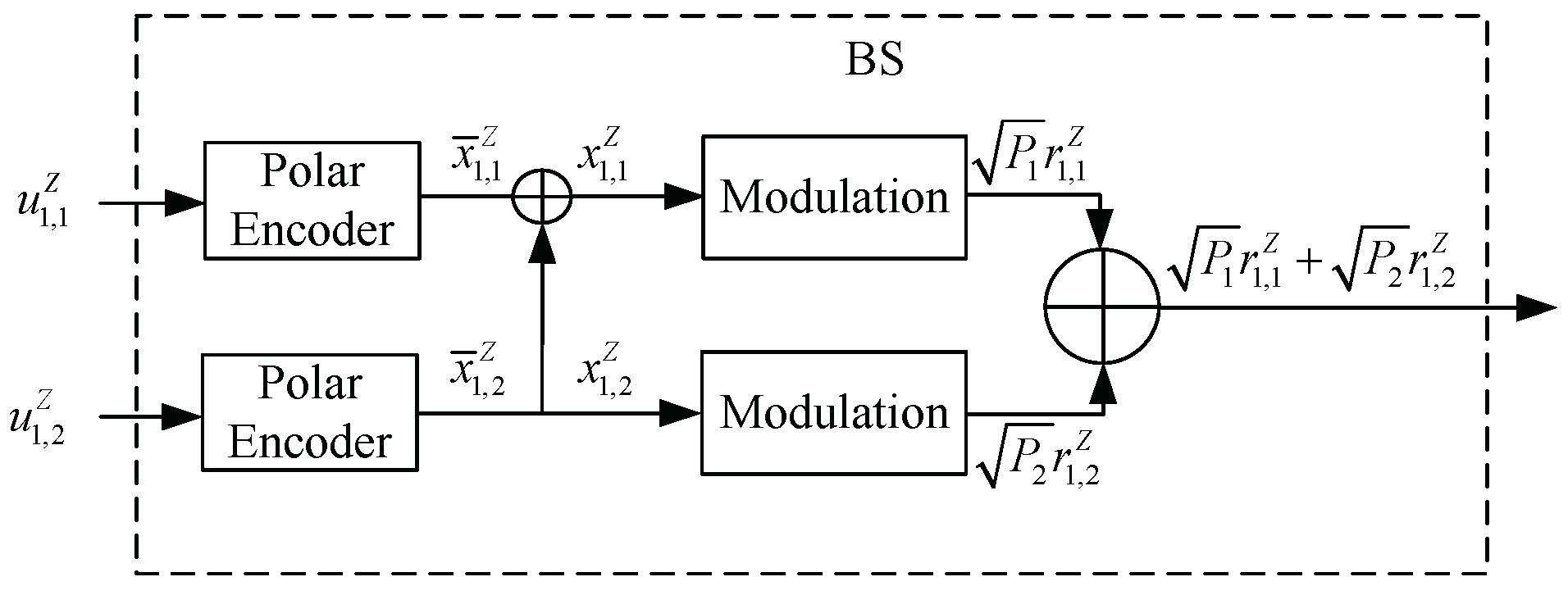
In particular, from the encoding principles in (7), the individual polar coding of length-Z for two users at the BS is equivalently transformed to a single polar coding of a larger length N, , as shown in Figure 2. Thus, at the BS, we can have the sub-codeword as
which is also the XORed signal of the two user codewords. Similarly, we can generate the sub−codeword of as
Then, the is BPSK−modulated to , , which are then superimposed and sent to the users. In user node s, the i−th received signal is given by
We define a set that collects four possible superimposed signals at user s as , where the j−th element in has the a priori probability , . At the user s, the probability of the received given the transmit signal is
where is a normalization factor that ensures . Moreover, we define another XOR-ed message for the superimposed signals, . Table 1 summarizes the PNC mapping rules for the coded bit and the received signal.
At the user s, we use , and to denote the initial LLRs of the i-th bit in , and , respectively, which can be computed by
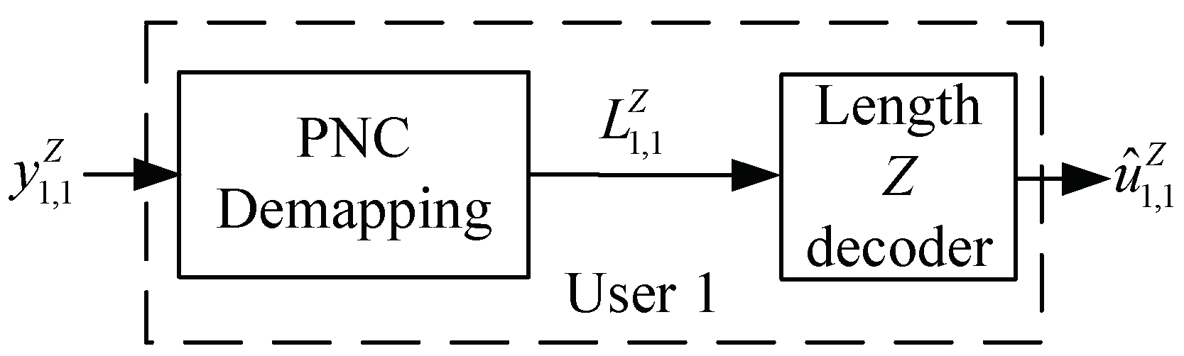
At User 1, from (8) and (9), we can see that the message can be derived from the XORed message : i.e.,
Then, the i-th initial LLR values for can be given by
Afterward, the LLR vector is fed into the polar decoder with codelength Z to estimate the source bits , as shown in Figure 3.
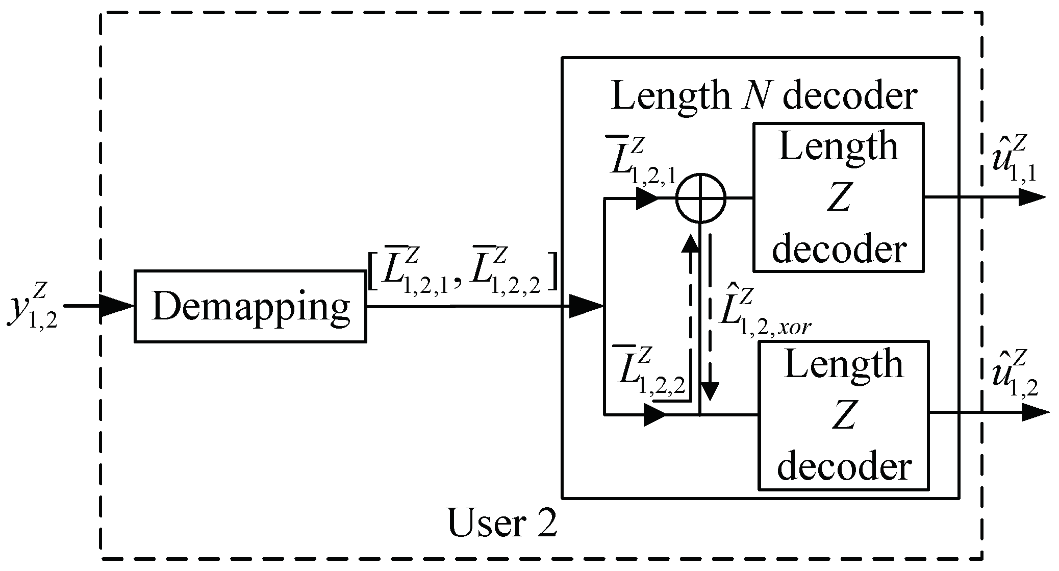
From (7), a polar code with codelength is constructed for User 2. As shown in Figure 4, denotes the initial LLR vector of this code, , and the i-th initial value is given by
where and denote the initial LLR values of and , respectively.
In this case, we can recover the source bits at User 2 in the polar decoder with length N. We can decode with the initial LLR in the polar decoder. In particular, we can recover the source bits in two ways. First, the source bit can be directly decoded by using in the length-Z polar decoder. Second, by the characteristics of polar decoding, let denote the LLR value of the XORed message of and [25]. We can see that can also be used to decode . Thus, and can be combined and then fed into the length-Z polar decoder to estimate .
3.2. Information-Theoretic Finite-Length Code Performance
Given , by using SIC, the received signal-to-interference-plus-noise ratio (SINR) at User 1 to detect the message of and User 2 to detect the message of in PC−SIC can be given by [26]
and
In PN−DNOMA, the BS transmits the superimposed message of the XORed message of two users and the message of the weak User 2. Thus, the XORed signal of the two transmitted messages is the message of User 1. From (14), we used the PNC mapping rule to obtain the information of User 1. By applying the cut−set theorem, the transmission rate of the XORed signal of the two transmitted messages of User 1 is given by
where denotes the code rate of the XORed signal in User 1 and and denote the received SINR at User 1 to detect the message of and , respectively [27,28]. Thus, the received SINR to detect the message of in PN−DNOMA is
At User 2, from the polar decoding principle and Figure 4, both and can obtain the source bits by utilizing the polar decoder with codelength Z, respectively. We assumed that the message from the BS is resolvable at User 2. Recall that we have two ways to decode the message of User 2. Let and denote the received SINRs in these two decoding methods, respectively, which can be merged by maximal ratio combining (MRC) [29]. Thus, the overall SINR of User 2’s message in PN-DNOMA after MRC is
As pointed out by [30], the decoding error probability at the receiver is non−negligible when the blocklength is finite. At user s, taking into account the impact of the non-zero error probabilities on decoding, we adopted the effective error probability , given by
where denotes the received SINR over the PC−SIC and PN−DNOMA schemes, denotes the transmission rate, and is the channel dispersion parameter, given by
Furthermore, from the trade-off between the error probability and transmission rate, we used the effective throughput to evaluate the system with a finite blocklength. Mathematically, the effective throughput is defined by [31]
In this system, our objective is to achieve user fairness and maximize the effective throughput by setting the power , . Thus, the optimization for both PN−DNOMA and PC−SIC can be formulated as
where is the variable set that needs to be determined by PN−DNOMA and PC-SIC, respectively.
4. Simulation Results
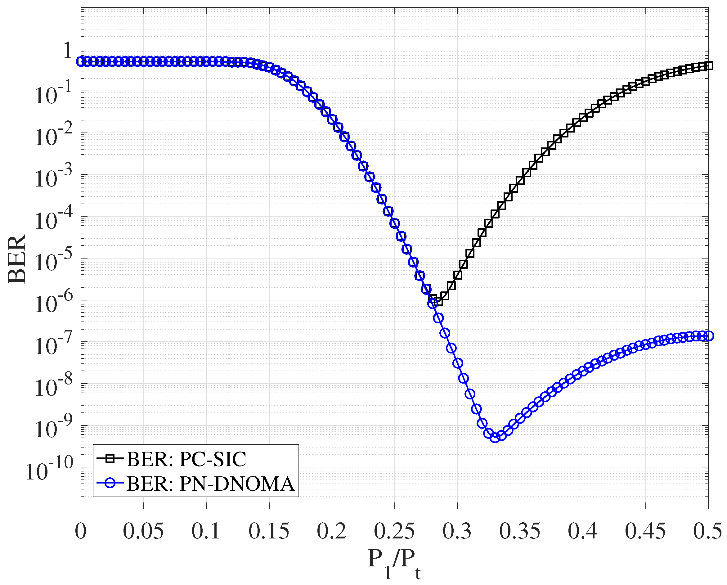
This section simulates the error performances of the two-user downlink NOMA over quasi-static Rayleigh fading channels with , , and . Figure 5 shows the decoding error probability of PN−DNOMA and PC−SIC [12] with different power allocation ratios, at a code rate of 3/4 and SNR = 18 dB, respectively. Note that and are the optimal power allocation ratios for PN−DNOMA and PC−SIC, respectively. Moreover, the proposed PN−DNOMA shows a much lower error performance than the conventional PC−SIC when .
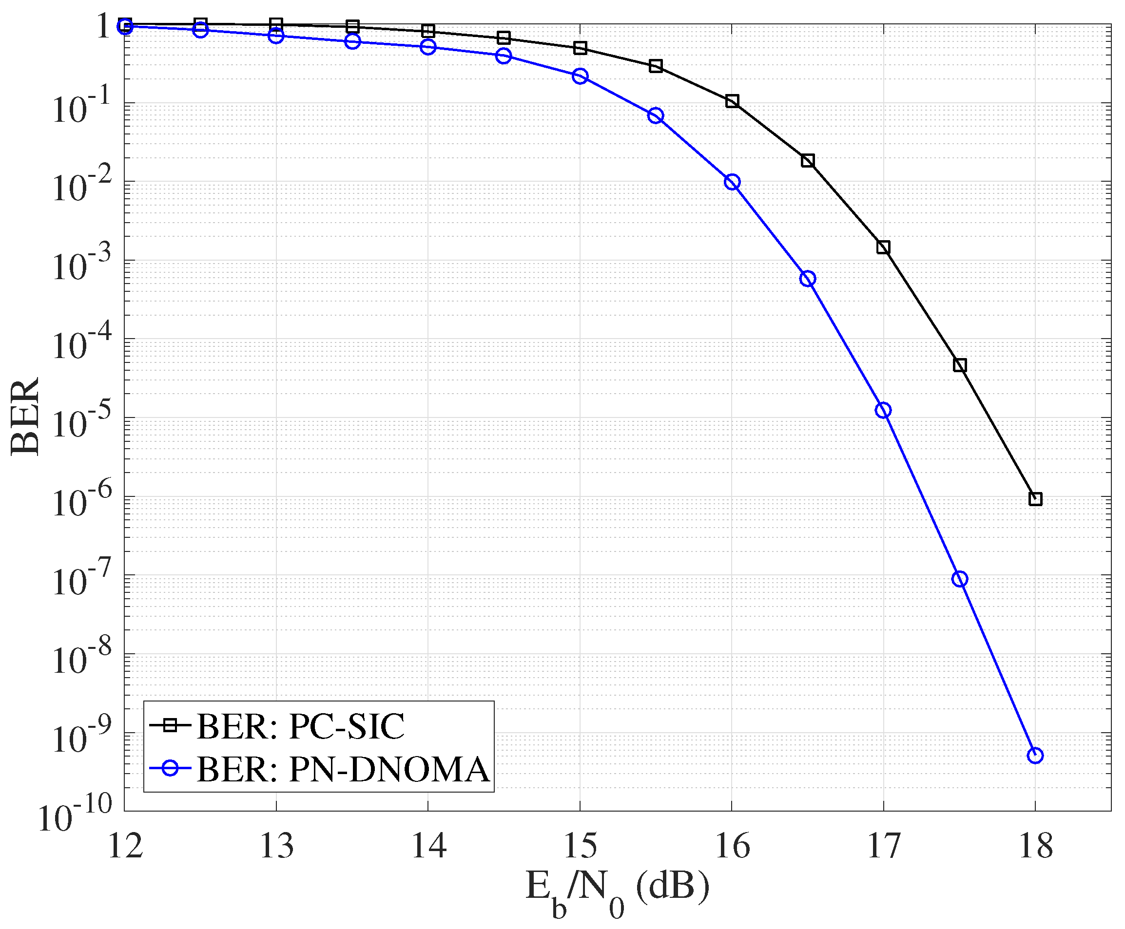
Figure 6 further compares the decoding error probability of PN−DNOMA and PC−SIC with their optimal power allocation, respectively. The proposed PN−DNOMA can achieve a significant performance gain of 0.75 dB over PC−SIC, at a BER of for .
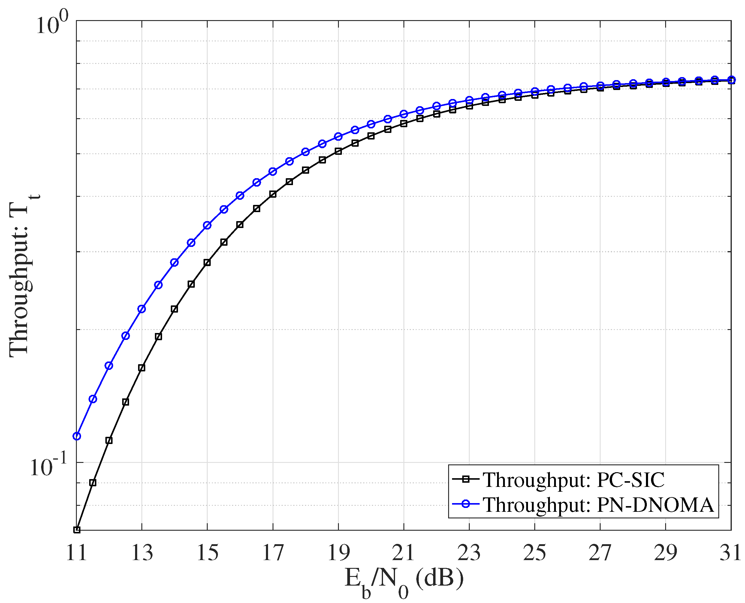
Figure 7 shows the effective throughput achieved by PN−DNOMA and PC−SIC, respectively, for and . Note that all the benchmark coding schemes were optimized for the given channels. We can see that the proposed PN−DNOMA has a larger throughput than PC−SIC in all the SNR region.
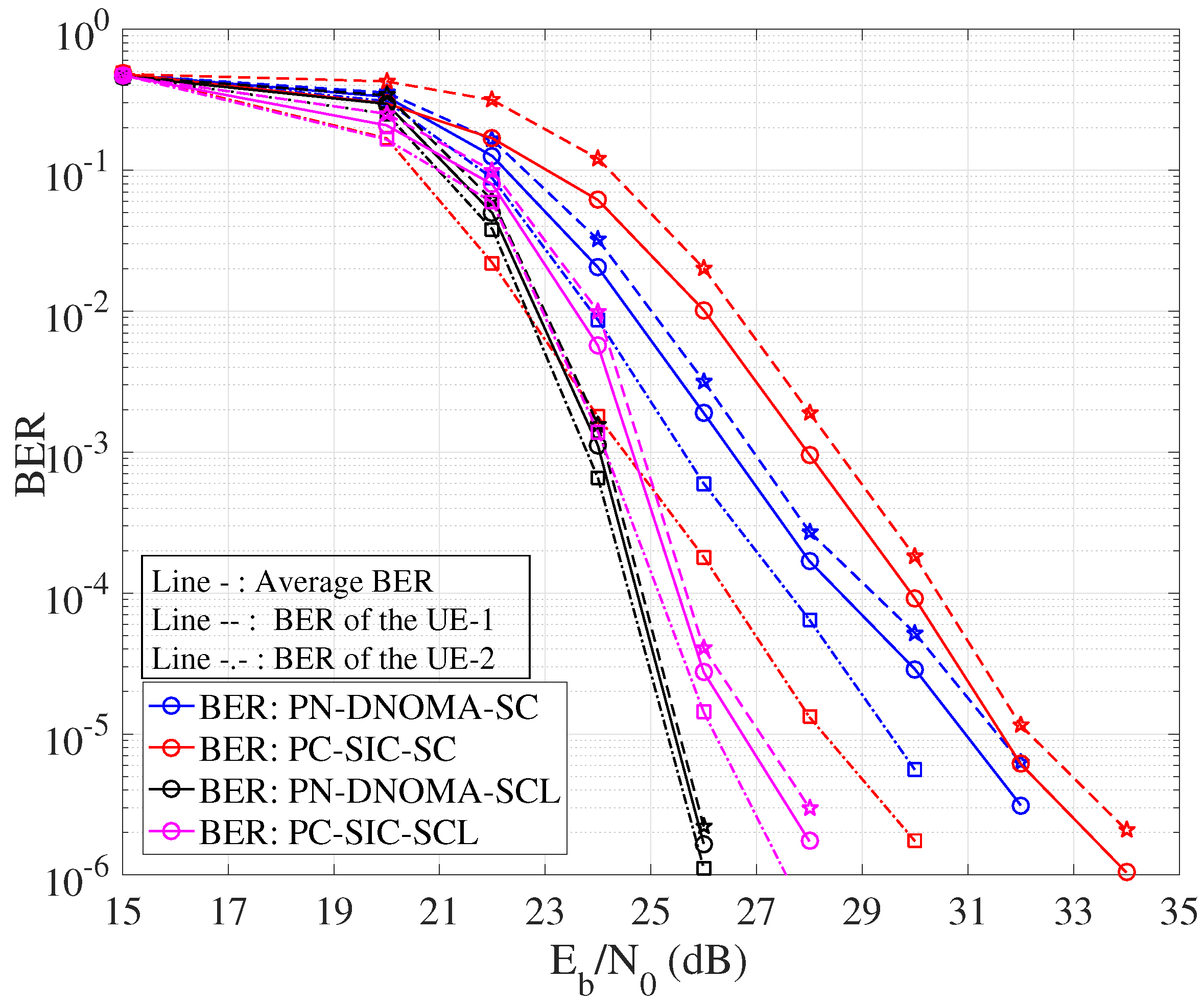
Figure 8 shows the error performance of PN−DNOMA and PC−SIC. We adopted the SC decoder and CA−SCL decoder at the user receivers, respectively. In particular, CA−SCL uses list size and CRC-8 with the generator polynomial . In PC−SIC, a joint successive cancellation (JSC) decoding is used [12]. The code rates of the two users are and for both PN−DNOMA and PC−SIC. The proposed PC−DNOMA can achieve a significant performance gain of 0.7 dB and 0.45 dB over PC−SIC for both SC and CA−SCL decoders, at a BER of , as shown in Table 2. Moreover, the performance gap of User 1 and User 2 in PN−DNOMA is smaller than that of PC−SIC, which demonstrates its enhanced user fairness.
With respect to the decoding complexity, the proposed PN−DNOMA consists of the PNC mapping operation and polar decoding with a length−Z decoder at User 1. In the receiver for User 2, we constructed a length−N polar decoder. Thus, the decoding complexity of PN−DNOMA with the SC and CA−SCL decoders is and , respectively, while in PC−SIC, a JSC decoding is used for User 1 and User 2, directly recovering the message of User 2 from the superimposed messages. Thus, the decoding complexity of PC−SIC with the SC and CA−SCL decoders is and , respectively. This means that the proposed PN−DNOMA can improve the decoding performance without increasing the complexity.
5. Conclusions
In this paper, we proposed a PN−DNOMA for two−user downlink NOMA systems, where the BS broadcasts the superimposed message of the XORed message of two users and the message of the weak User 2. The main finding of this paper is that, by exploiting the polarization effect and PNC principle, we can use polar decoding to directly recover the message of User 1, while for User 2, a long−length polar code from the superimposed message can be constructed. In this way, the message of User 2 can be recovered by this polar code as a multiuser decoding. The channel polarization effect of the polar decoding in PN−DNOMA is greatly improved. The simulation results showed that the proposed PC−DNOMA can achieve significant performance gains of 0.7 dB and 0.45 dB over the conventional PC−SIC for the SC and CA−SCL decoders, at a BER of , respectively, and the user fairness is also enhanced over two−user NOMA systems. Furthermore, as a potential direction, it is worthwhile to mention that the proposed scheme can be extended to more generalized M−user NOMA, , to enhance the system performance in the future.
Author Contributions
Conceptualization, Z.X. and P.C.; methodology, Z.X. and P.C.; software, Z.X.; validation, Z.X. and P.C.; formal analysis, Z.X. and Y.L.; resources, Z.X.; data curation, Z.X.; writing, Z.X; original draft preparation, Z.X.; investigation, Z.X.; writing, Z.X.; review and editing, Z.X. and P.C.; visualization, Z.X. and Y.L.; project administration, Z.X., Y.L. and P.C.; funding acquisition, Z.X., Y.L. and P.C.; supervision, Z.X., Y.L. and P.C. All authors have read and agreed to the published version of the manuscript.
Funding
This work was supported by the Natural Science Fund of China under Grants 61871132 and 62171135 the Industry-University Research Project of Education Department Fujian Province 2020.
Institutional Review Board Statement
Not applicable.
Informed Consent Statement
Not applicable.
Data Availability Statement
The data are contained within the article.
Conflicts of Interest
The authors declare no conflict of interest.
Abbreviations
The following abbreviations are used in this manuscript:
| PNC | Physical network coding |
| PN-DNOMA | A joint PNC for two−user downlink non−orthogonal multiple access |
| NOMA | Non−orthogonal multiple access |
| SIC | Successive interference cancellation |
| PA | Power allocation |
| BS | Base station |
| PC-SIC | A joint polar decoding and SIC decoding strategy |
| NCMA | Network-coded multiple access |
| SC | Successive cancellation |
| CS-SCL | Cyclic−redundancy−check−aided SC−list |
| CSIT | Channel state information at the transmitter |
| B-DMC | Binary−input discrete memoryless channel |
| SINR | Signal−to−interference−plus−noise ratio |
| JSC | Joint successive cancellation |
| QAM | Quadrature amplitude modulation |
| MF | Matched-filter |
References
- Dai, L.; Wang, B.; Yuan, Y.; Han, S.; Chih-lin, I.; Wang, Z. Non-orthogonal multiple access for 5G: Solutions, challenges, opportunities, and future research trends. IEEE Commun. Mag. 2015, 53, 74–81. [Google Scholar] [CrossRef]
- Fang, F.; Zhang, H.; Cheng, J.; Leung, V.C. Energy-efficient resource allocation for downlink non-orthogonal multiple access network. IEEE Trans. Commun. 2016, 64, 3722–3732. [Google Scholar] [CrossRef]
- Cover, T. Broadcast channels. IEEE Trans. Inf. Theory. 1972, 18, 2–14. [Google Scholar] [CrossRef] [Green Version]
- Sun, Q.; Han, S.; Chin-Lin, I.; Pan, Z. On the ergodic capacity of MIMO NOMA systems. IEEE Wirel. Commun. Lett. 2015, 4, 405–408. [Google Scholar] [CrossRef]
- Assaf, T.; Al-Dweik, A.J.; El Moursi, M.S.; Zeineldin, H.; Al-Jarrah, M. Exact bit error-rate analysis of two-user NOMA using QAM with arbitrary modulation orders. IEEE Commun. Lett. 2020, 24, 2705–2709. [Google Scholar] [CrossRef]
- Yu, W.; Jia, H.; Musavian, L. Joint adaptive M-QAM modulation and power adaptation for a downlink NOMA network. IEEE Trans. Commun. 2021, 70, 783–796. [Google Scholar] [CrossRef]
- Sun, Z.; Jing, Y.; Yu, X. NOMA design with power-outage tradeoff for two-user systems. IEEE Wirel. Commun. Lett. 2020, 9, 1278–1282. [Google Scholar] [CrossRef] [Green Version]
- Liu, K.H. Quasi-Degradation Probability of Two-User NOMA Over Rician Fading Channels. IEEE Trans. Veh. Technol. 2021, 70, 3514–3524. [Google Scholar] [CrossRef]
- Zaidel, B.M.; Shental, O.; Shamai, S. Beyond equal-power sparse NOMA: Two user classes and closed-form bounds on the achievable region. Entropy 2022, 24, 227. [Google Scholar] [CrossRef] [PubMed]
- Li, S.; Derakhshani, M.; Lambotharan, S.; Hanzo, L. Outage probability analysis for the multi-carrier NOMA downlink relying on statistical CSI. IEEE Trans. Commun. 2020, 68, 3572–3587. [Google Scholar] [CrossRef] [Green Version]
- Tse, D.; Viswanath, P. Fundamentals of Wireless Communication; Cambridge University Press: Cambridge, UK, 2005. [Google Scholar]
- Yao, J.; Zhang, Q.; Qin, J. Joint Decoding in Downlink NOMA Systems with Finite Blocklength Transmissions for Ultra-Reliable Low-Latency Tasks. IEEE Internet Things J. 2022. [Google Scholar] [CrossRef]
- Chung, K. Correlated superposition coding: Lossless two-user NOMA implementation without SIC under user-fairness. IEEE Wirel. Commun. Lett. 2021, 10, 1999–2003. [Google Scholar] [CrossRef]
- Arikan, E. Channel polarization: A method for constructing capacity-achieving codes for symmetric binary-input memoryless channels. IEEE Trans. Inf. Theory. 2009, 55, 3051–3073. [Google Scholar] [CrossRef]
- Zhang, S.; Liew, S.C.; Lam, P.P. Hot topic: Physical-layer network coding. In Proceedings of the 12th Annual International Conference on Mobile Computing and Networking, Los Angeles, CA, USA, 23–29 September 2006; pp. 358–365. [Google Scholar]
- Chen, P.; Shi, L.; Fang, Y.; Lau, F.C.M.; Cheng, J. Rate-Diverse Multiple Access over Gaussian Channels. IEEE Trans. Wirel. Commun. 2023, 1, 1. [Google Scholar] [CrossRef]
- Xie, Z.; Chen, P.; Mei, Z.; Long, S.; Cai, K.; Fang, Y. Polar-coded physical layer network coding over two-way relay channels. IEEE Commun. Lett. 2019, 23, 1301–1305. [Google Scholar] [CrossRef]
- Khan, A.S.; Chatzigeorgiou, I.; Lambotharan, S.; Zheng, G. Network-coded NOMA with antenna selection for the support of two heterogeneous groups of users. IEEE Trans. Wirel. Commun. 2019, 18, 1332–1345. [Google Scholar] [CrossRef] [Green Version]
- Zhang, Z.; Qu, H.; Zhao, J.; Wang, W. Contract Theory-Based Incentive Mechanism for Full Duplex Cooperative NOMA with SWIPT Communication Networks. Entropy 2021, 23, 1161. [Google Scholar] [CrossRef] [PubMed]
- Cui, J.; Ding, Z.; Fan, P. A novel power allocation scheme under outage constraints in NOMA systems. IEEE Signal Process. Lett. 2016, 23, 1226–1230. [Google Scholar] [CrossRef] [Green Version]
- Wang, H.; Dong, J.; Tang, K.; Shi, H. Outage Performance Analysis of NOMA in Wireless Powered Cognitive Radio Networks with AF and DF Relaying Techniques. Entropy 2021, 23, 1463. [Google Scholar] [CrossRef] [PubMed]
- Lau, V.K.; Liu, Y.; Chen, T.A. Capacity of memoryless channels and block-fading channels with designable cardinality-constrained channel state feedback. IEEE Trans. Inf. Theory. 2004, 50, 2038–2049. [Google Scholar] [CrossRef]
- Arikan, E. Systematic polar coding. IEEE Commun. Lett. 2011, 15, 860–862. [Google Scholar] [CrossRef] [Green Version]
- Trifonov, P. Efficient design and decoding of polar codes. IEEE Trans. Commun. 2012, 60, 3221–3227. [Google Scholar] [CrossRef] [Green Version]
- Balatsoukas-Stimming, A.; Parizi, M.B.; Burg, A. LLR-based successive cancellation list decoding of polar codes. IEEE Trans. Signal Process. 2015, 63, 5165–5179. [Google Scholar] [CrossRef] [Green Version]
- Wei, Z.; Ng, D.W.K.; Yuan, J.; Wang, H.M. Optimal resource allocation for power-efficient MC-NOMA with imperfect channel state information. IEEE Trans. Commun. 2017, 65, 3944–3961. [Google Scholar] [CrossRef] [Green Version]
- Zhang, S.; Liew, S.C.; Wang, H.; Lin, X. Capacity of two-way relay channel. In Proceedings of the Access Network; Springer: Berlin/Heidelberg, Germany, 2009; Volume 23, pp. 219–231. [Google Scholar]
- Nam, W.; Chung, S.Y.; Lee, Y.H. Capacity of the Gaussian Two-Way Relay Channel to Within 1/2 Bit. IEEE Trans. Inf. Theory. 2010, 56, 5488–5494. [Google Scholar] [CrossRef]
- Xu, B.; Xiang, Z.; Ren, P.; Guo, X. Outage performance of downlink full-duplex network-coded cooperative noma. IEEE Wirel. Commun. Lett. 2020, 10, 26–29. [Google Scholar] [CrossRef]
- Polyanskiy, Y.; Poor, H.V.; Verdú, S. Channel coding rate in the finite blocklength regime. IEEE Trans. Inf. Theory. 2010, 56, 2307–2359. [Google Scholar] [CrossRef]
- Sun, X.; Yan, S.; Yang, N.; Ding, Z.; Shen, C.; Zhong, Z. Short-packet downlink transmission with non-orthogonal multiple access. IEEE Trans. Wirel. Commun. 2018, 17, 4550–4564. [Google Scholar] [CrossRef] [Green Version]
Figure 1.
Block diagram of a two-user downlink NOMA system.

Figure 2.
Block diagram of the transmitter in two-user PN−DNOMA.

Figure 3.
Block diagram of the receiver at User 1 in PN−DNOMA.

Figure 4.
Block diagram of the receiver at User 2 in PN−DNOMA.

Figure 5.
Error performance of two−user PN−DNOMA and PC−SIC with different power allocations at SNR = 18 dB.
Figure 5.
Error performance of two−user PN−DNOMA and PC−SIC with different power allocations at SNR = 18 dB.

Figure 6.
Error performance of PN−DNOMA and PC−SIC with the optimal power allocation, over two−user downlink NOMA.
Figure 6.
Error performance of PN−DNOMA and PC−SIC with the optimal power allocation, over two−user downlink NOMA.

Figure 7.
Effective throughput achieved by PN−DNOMA and PC−SIC, over two−user downlink NOMA.

Figure 8.
Error performance of PN−DNOMA and PC−SIC over two−user downlink NOMA.


Table 1.
Mapping rules for code bits and received signals.
| j | S | |||||
|---|---|---|---|---|---|---|
| 0 | 0 | 0 | 0 | |||
| 1 | 1 | 0 | 1 | |||
| 2 | 0 | 1 | 1 | |||
| 3 | 1 | 1 | 0 |
Table 2.
Error performance and decoding complexity of PN−DNOMA and PC−SIC over two−user downlink NOMA.
Table 2.
Error performance and decoding complexity of PN−DNOMA and PC−SIC over two−user downlink NOMA.
| Decoder | ||||
|---|---|---|---|---|
| SC Decoder | CA−SCL Decoder | |||
| PC−SIC | PN−DNOMA | PC−SIC | PN−DNOMA | |
| BER: | 30.1 (dB) | 28.3 (dB) | 25.6 (dB) | 24.5 (dB) |
| BER: | 31.8 (dB) | 30.9 (dB) | 26.7 (dB) | 25.6 (dB) |
| Decoding Complexity | ||||
Disclaimer/Publisher’s Note: The statements, opinions and data contained in all publications are solely those of the individual author(s) and contributor(s) and not of MDPI and/or the editor(s). MDPI and/or the editor(s) disclaim responsibility for any injury to people or property resulting from any ideas, methods, instructions or products referred to in the content. |
© 2023 by the authors. Licensee MDPI, Basel, Switzerland. This article is an open access article distributed under the terms and conditions of the Creative Commons Attribution (CC BY) license (https://creativecommons.org/licenses/by/4.0/).
Share and Cite
MDPI and ACS Style
Xie, Z.; Chen, P.; Li, Y. Joint Design of Polar Coding and Physical Network Coding for Two−User Downlink Non−Orthogonal Multiple Access. Entropy 2023, 25, 233. https://doi.org/10.3390/e25020233
AMA Style
Xie Z, Chen P, Li Y. Joint Design of Polar Coding and Physical Network Coding for Two−User Downlink Non−Orthogonal Multiple Access. Entropy. 2023; 25(2):233. https://doi.org/10.3390/e25020233
Chicago/Turabian StyleXie, Zhaopeng, Pingping Chen, and Yong Li. 2023. "Joint Design of Polar Coding and Physical Network Coding for Two−User Downlink Non−Orthogonal Multiple Access" Entropy 25, no. 2: 233. https://doi.org/10.3390/e25020233
Note that from the first issue of 2016, this journal uses article numbers instead of page numbers. See further details here.